Yellow Diamond Electrical Control System
Water Level Switch
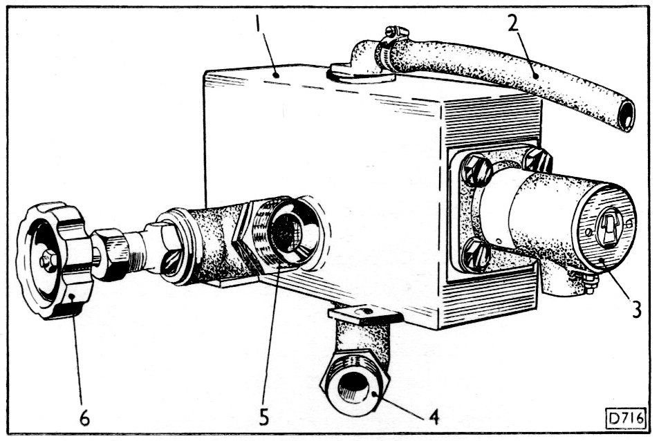
1. Low water tank
2. Vent pipe from radiator
3. Water level indication switch
4. Inlet pipe from supply tank
5. Outlet pipe to radiator
6. Stop Cock
Description
From the BUT A Series Service Manual:
The water level switch is mounted on the water tank and is attached to a float which; when the water in the tank reaches a low level, operates the switch thereby actuating the engine shut-down solenoid and stopping the engine.
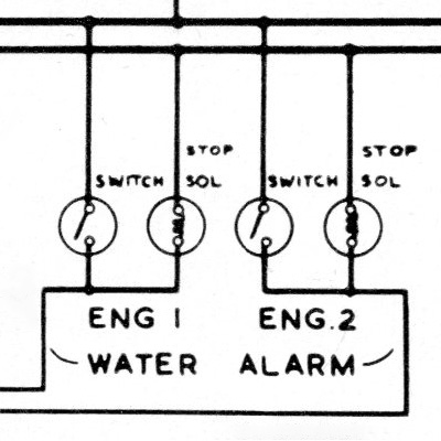
Schematics
Schematics showing the electrical connections, as shown in the BUT A series maintenance manual.
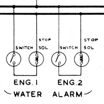
On yellow diamond vehicles were two methods of stopping the engines: via the throttle motor by only energising the throttle 1 circuit, this put the fuel pump into the cut fuel position; and with a stop solenoid which was directly connected to the fuel pump. The solenoid option was needed for when an engine needed to be shut down while in motion, as energising throttle 1 would not be effective if other throttle circuits were active.
On Derby Lightweights (the first diagram) the water level switch was the only item that controlled the shut down solenoid and simply connected the train + to the solenoid (the side of which was connected to the train - cricuit).
On the Met-Camm Lighweights (second diagram) the water level switch was connected in exactly the same way but the + feed to the solenoid could also come from the engine stop buttons on the underframe.
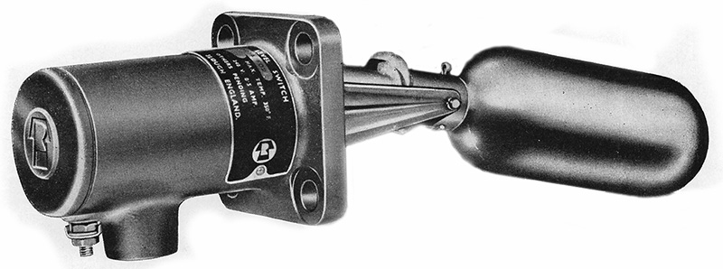
Mobrey Switch
A typical water-level switch was the 'Mobrey Switch', this example was supplied by Ronald Trist & Co. Ltd.: