Yellow Diamond Electrical Control System
Electro-Pneumatic Valves
Each power car had two boxes containing electro-pneumatic (E.P.) Valves located on the underframe.
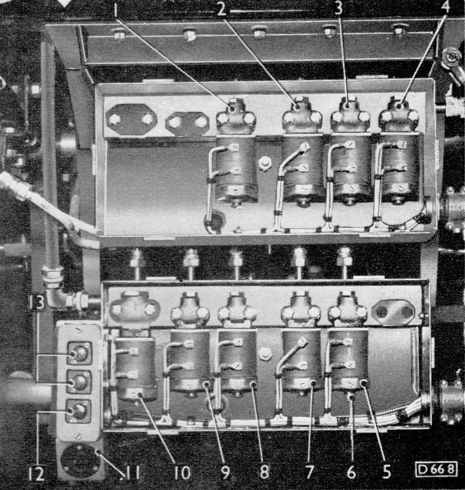
1. Gearbox E.P. Valve—1st Speed
2. Gearbox E.P. Valve—2nd Speed
3. Gearbox E.P. Valve—3rd Speed
4. Gearbox E.P. Valve—4th (Top) Speed
5. Final Drive E.P. Valve—Reverse Speed
6. E.P. Valve Hand Testing Button
7. Final Drive E.P. Valve—Forward Speed
8. Throttle E.P. Valve—No. 3
9. Throttle E.P. Valve—No. 2
10. Throttle E.P. Valve—No. 1
11. Inspection Lamp Socket
12. Engine Stop Button
13. Engine Start Buttons
Description
From the BUT A Series Service Manual:
Each car is provided with a number of electro-pneumatic valves for controlling the supply of compressed air to the actuating mechanism for gear selection and engagement, the engine throttle control motors and the engagement of forward or reverse gears in the final drive units.
These valves are of two types, "ON" and "OFF." The "ON" type WILL pass air when the solenoid is energised, whereas the "OFF" type WILL NOT pass air when the solenoid is energised. The type designation should appear stamped on a raised portion on the underside of the valve; also on the underside is a push button for operating the valve by hand for testing.
Each electro-pneumatic valve embodies a needle valve which either opens or closes—depending upon the type—a short passage connecting an air feed pipe to a delivery pipe which leads to the actuating mechanism concerned. The needle valve is operated by a loosely fitting plunger inside the core of a solenoid whenever the latter is energised, and works against the pressure in the air line in addition to that exerted by a small coil spring. The design of the connecting passage and the plunger top is such that any air leaking past the valve is discharged to atmosphere.
Schematic
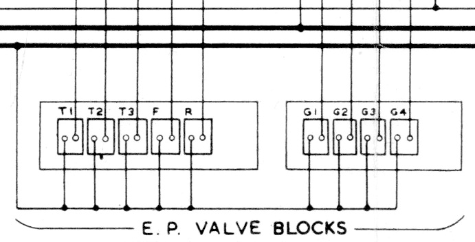
Schematic showing the electrical connections, as shown in the BUT A series service manual.
All valves have a common negative feed from the "Train -" circuit. Each valve is also connected to the appropriate operating circuit (Throttle 1, 2, 3, Forward / Reverse, Gear 1, 2, 3, 4) providing the positive feed to the valve coil through either the cab controls or jumper sockets.
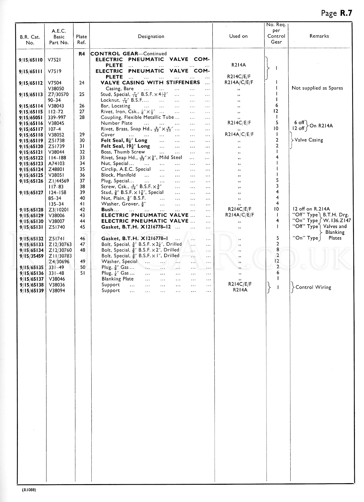
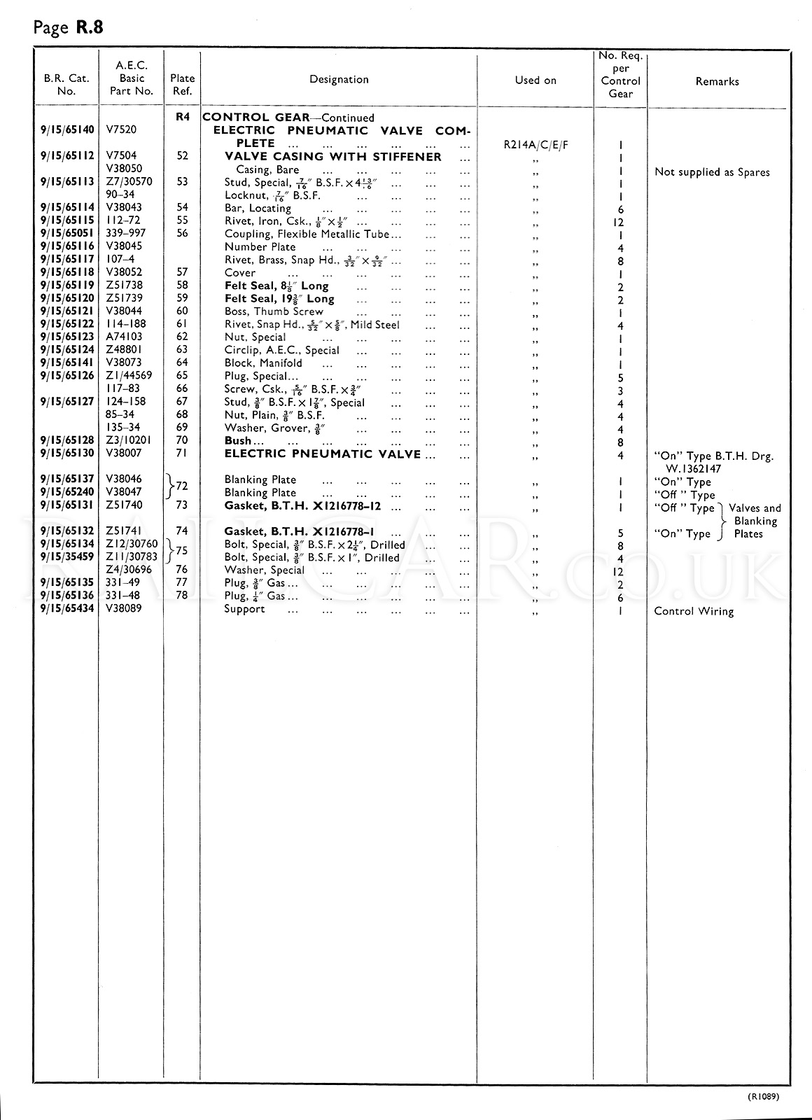
Exploded View
Taken from the AEC Spare Parts Catalogue.