Yellow Diamond Electrical Control System
Throttle Controller
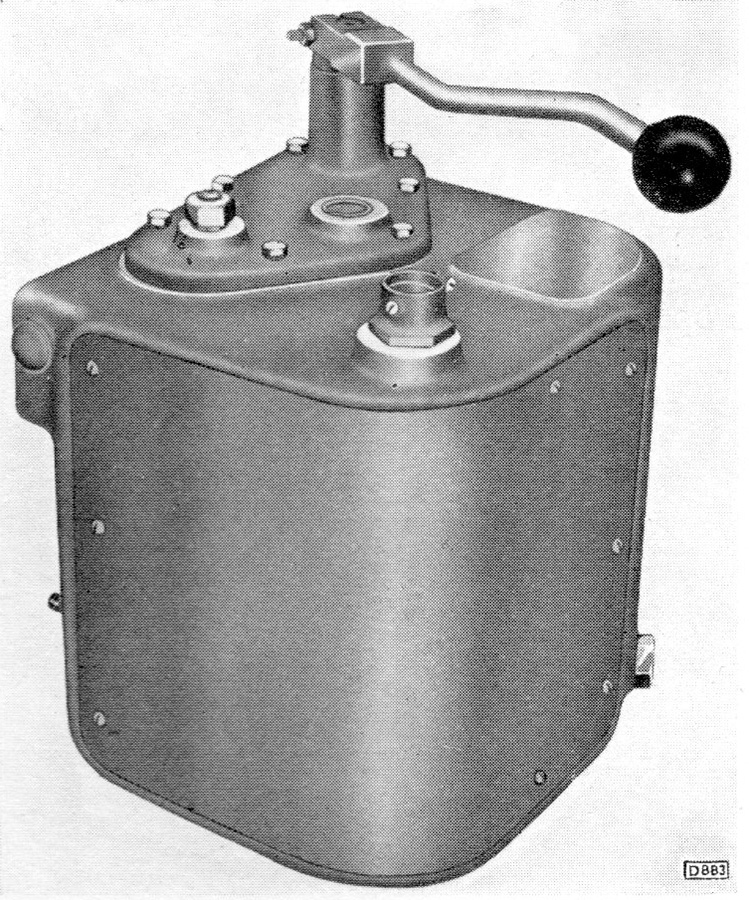
Combined Throttle Controller and "Deadman's Control"
This was fitted to 79xxx series Yellow Diamond and White Circle vehicles. One was provided per cab, it would be to the drivers left side on the control desk.
Description
From the BUT 'A' Type Units Manual:
The throttle control lever is connected by linkage to a shaft which carries a number of cams. Each cam closes an electrical contact, when in the appropriate position (depending on the position of the control lever), which in turn operates the solenoid in the corresponding electro-pneumatic valve, thus actuating the throttle control motors.
A notched locating plate on the end of the camshaft, which engages with the spring-loaded pin, retains the camshaft in any selected position, unless the driver releases the control lever, in which case, the camshaft will turn under the action of a return spring and select "Idling" and "deadman's" position.
For the "deadman's" control valve see Gresham and Craven's "Instructions for Gresham's Quick Release Vacuum Brake Equipment on British Railways Railcars."
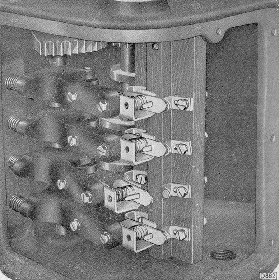
The second image shows the electrical contacts, with three of the four being made.
Maintenance for the throttle and gear controllers was noted in the BUT Manual as simply:
Clean the contacts by wiping them with a clean rag dipped in petrol. Apart from this the controllers require no maintenance.
At overhaul periods lightly smear all working parts with lubricant.
Schematic
As shown in the BUT A series maintenance manual.
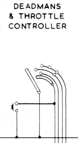
The bottom horizontal wire is a positive feed energised when the reversing lever is in place.
When the throttle handle is held down it will connect to the "Deadmans" circuit (terminal 25 on jumper terminals) in all positions and when pulled towards the driver to different throttle circuits (18/19/20 on jumper terminals).
Throttle circuits fed in each throttle position are:
1: Throttle 2
2: 1 + 3
3: 3
4: 2 + 3
The push button on the left was the deadman's holdover switch that would be on the opposite side of the cab from the drivers controls for token exchanges etc. and connects the "Deadmans" circuit to the common positive feed when the throttle handle was not being depressed.
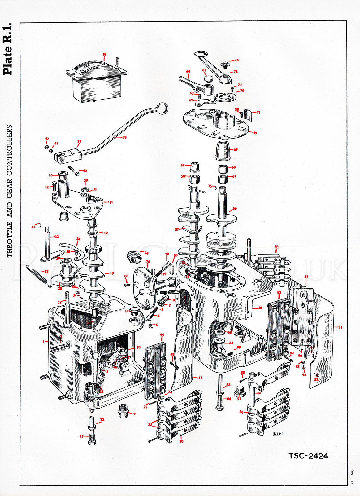
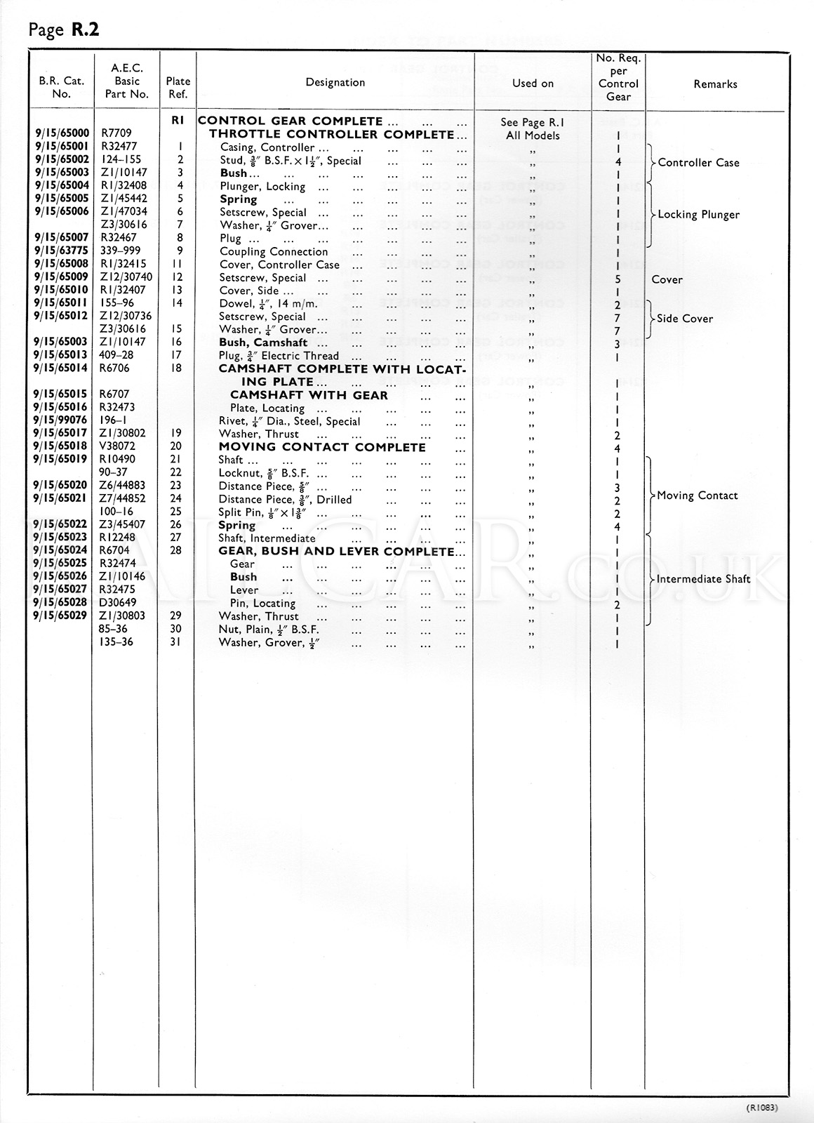
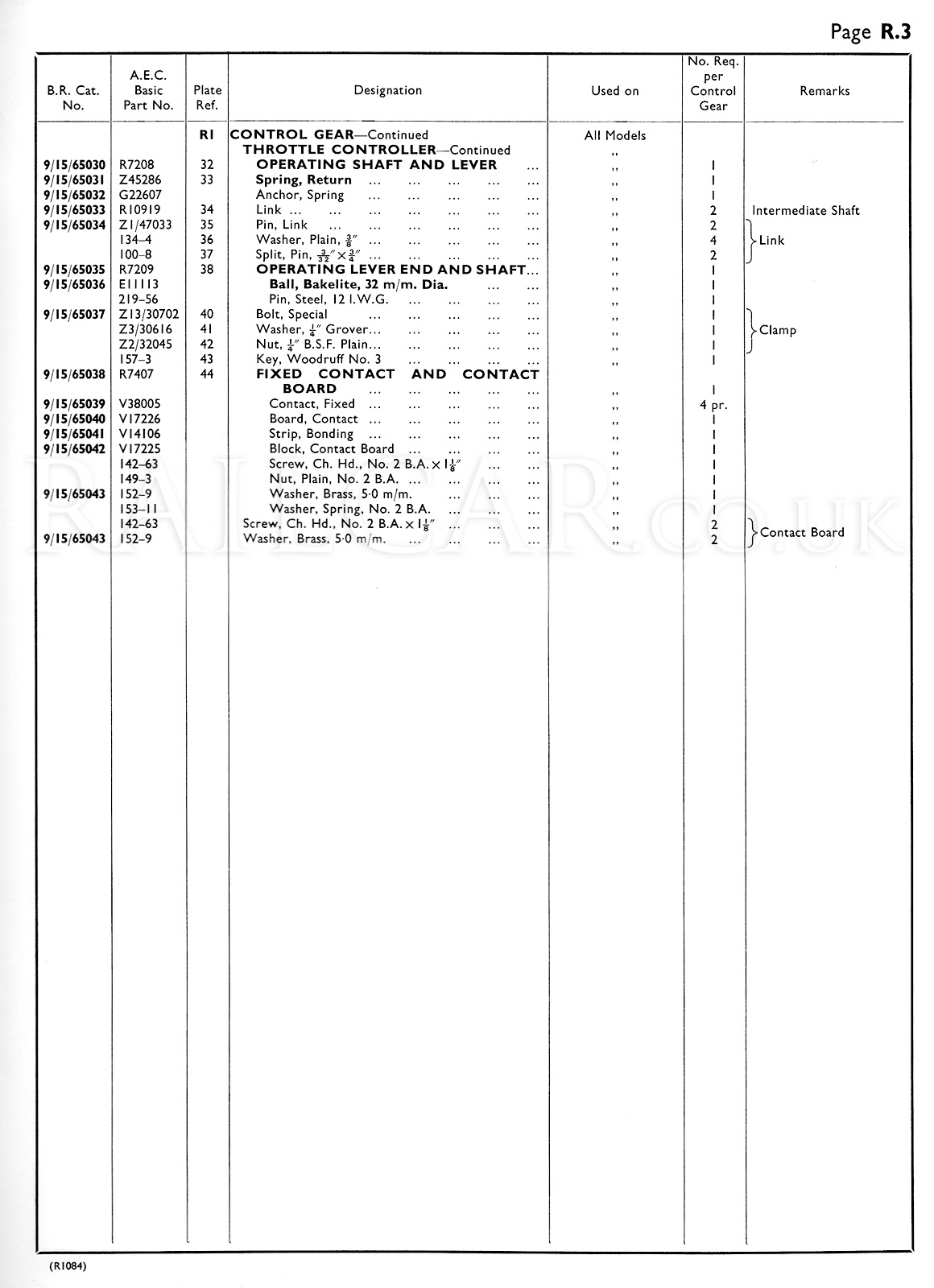
Exploded View
Taken from the AEC Spare Parts Catalogue.