
Yellow Diamond Electrical Control System
Air Pressure Switch (if fitted)
No image has been found showing what this switch was like on Yellow Diamond vehicles but from the description it is probably the same type as used on the Blue Square system.
Description
From the BUT A Series Service Manual:
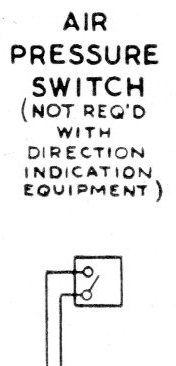
The air pressure switch is totally enclosed, its function being to indicate electrically, the state of the air pressure in each power car.
Fluctuation of air pressure in the system, operates the switch, which actuates an indicator light on the control panel in the driver's cab.
These lights are "on" when the switch cuts in and "off" when the switch cuts out.
Projecting from one side of the casing is a small trigger, which is integral with the switch and can be operated manually, if required, to test the circuit between the switch and lights.
Schematic
These schematics show the electrical connections, as shown in the BUT A series maintenance manual.
The first was for the early Derby Lighweights and simply connected the Train - circuit to the Air 1 circuit. This would light the Air 1 lamp on the air/axle display in the cab for the leading power car (if the gear lever was inserted to provide the + common feed to the lamps).
The Air 1 circuit was terminal 9 on the jumper at the rear of the power car (it would show as the number 1 air pressure indicator lamp on an adjacent driving trailer), but terminal 10 on the jumper at the front of the car - the change meant it lit the number 2 lamp in the cab of an adjacent set.
Later Derby Lightweights and the Met-Camm Lightweights had two air pressure switches (connected the air feeds from the forward/reverse ep-valves) and the electrical circuits were routed through switches on the final drives. This ensured that there was sufficient air pressure to engage the final drive and that both drives were in the same direction for the lamp in the cab to illuminate.
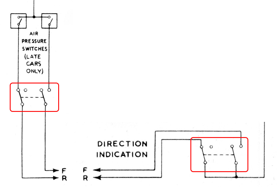
Both switches (top left) were connected to the "Train -" circuit (wire 17 at the jumper terminals). With sufficient air pressure the switches closed providing the positive feed through the "Direction Indication Switches" on each final drive, highlighted in red. These in turn fed circuit "Air 1" that controlled the number 1 "Air Pressure" indication lamp in the cab.