Yellow Diamond Electrical Control System
Control Unit
On the number one (the driver) side of power cars there was a large box of electrical items between the battery box (just out of sight on the left in the image) and the engine. It is circled below:
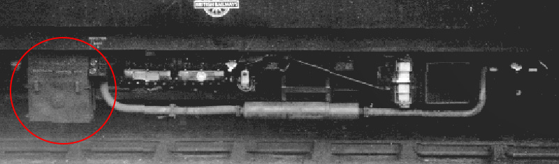
On the box lid was a circular cover which pivoted at the top for easy access to the battery isolating switch inside. The box cover was held in place by wing nuts and the two handles allowed it to be lifted off for access to the fuses inside.
The equipment differed depending on whether vehicles had engine mounted dynamos (left, early Derby Lightweights), or frame mounted dynamos (right, Met-Camm Lightweights and later Derby Lightweights 79118-49, 79169-81, 79184-93 and 79900/1).
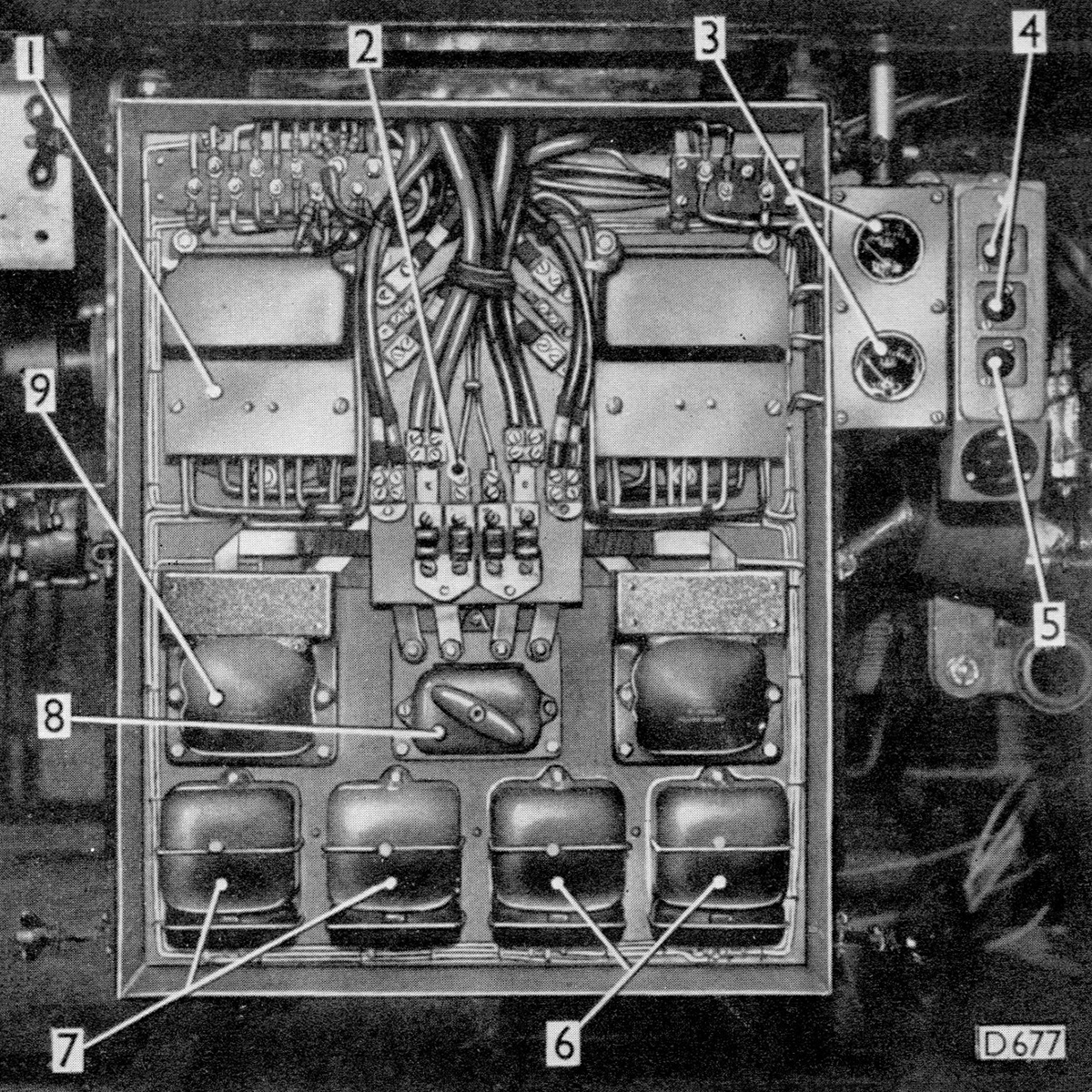
- Control Unit (two)
- Battery Charging and Supply Fuses
- Dynamo Ammeters
- Engine Auxiliary Starter Buttons
- Engine Auxiliary Stop Button
- Starter Relays
- Starter Isolating Relays
- Battery Isolating Switch
- Starter Isolating Switch (two)
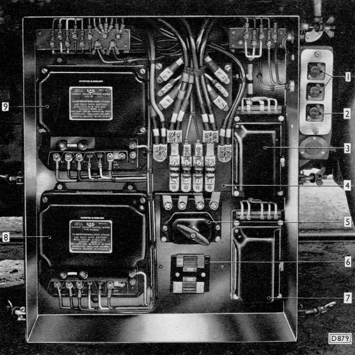
- Engine Auxiliary Starter Buttons
- Engine Auxiliary Stop Button
- Starter Isolating Relay - No.1 Engine
- Battery Charging and Supply Fuses
- Battery Isolating Switch
- Spare Fuses
- Starter Isolating Relay - No.2 Engine
- Control Unit - No.2
- Control Unit - No.1
Description
From the BUT A Series Service Manual:
A conrol unit is used in conjunction with each dynamo and is mounted in the electrical control box adjacent to Number 1 engine.
Each control unit houses a double-element regulator, cut-out, main fuse and terminals for battery, dynamo, load, ammeter and starter solenoid switch connections. The regulator operates on the current voltage control system whereby the battery, if partially discharged, is charged at a constant current until its voltage reaches a predetermined value, when the charging changes to constant voltage control. Normally only one of the regulator elements, therefore, is in operation at any one time.
Spare fuse strips are carried in a clip on the inside of the fuse and terminal cover plate, which is attached to the main cover by two captive screws.
The two ammeter terminals are shunted, to produce an instrument deflection current of 1.875 milliamperes for each ampere load current.
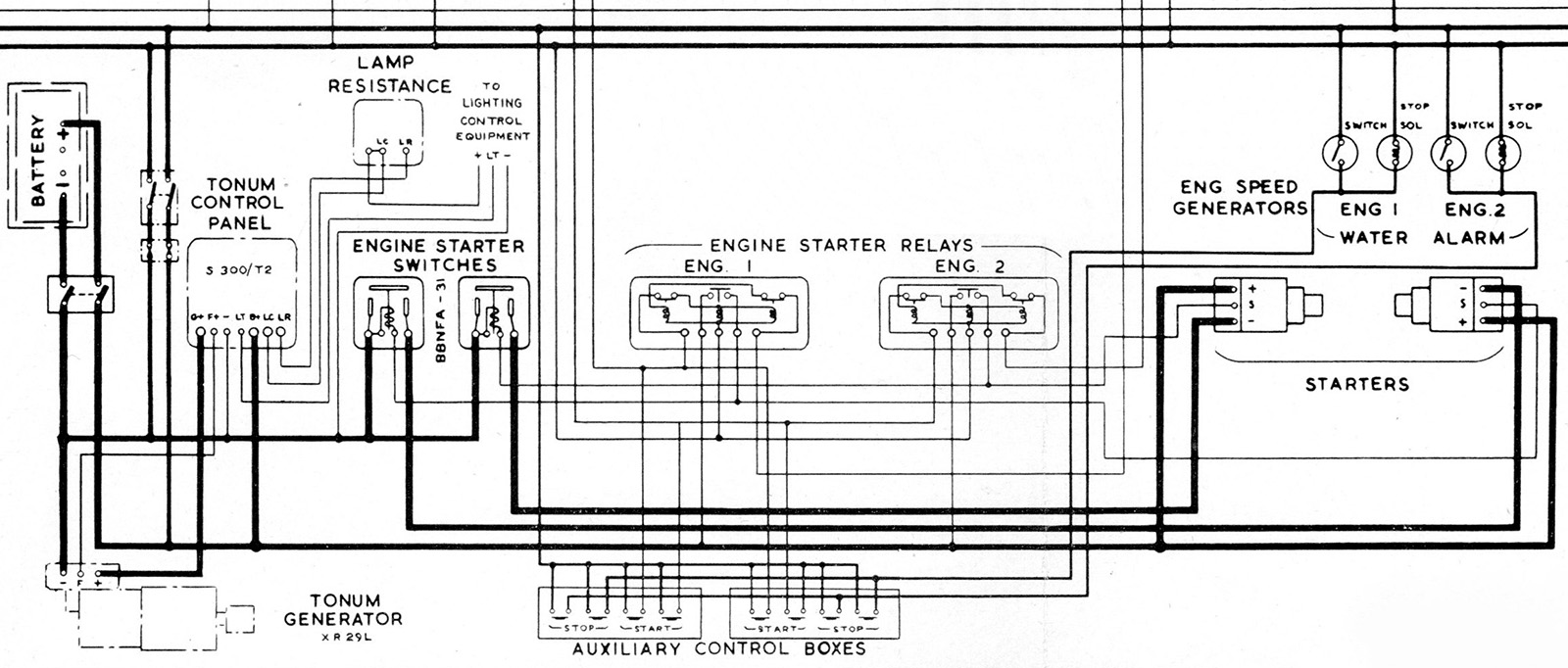
Schematic
These diagrams are extracted from the BUT A series manual, and show most of the items in the control box, and a few other items that are not.
The first shows the wiring for the Derby Lighweights with engine mounted dynamos.
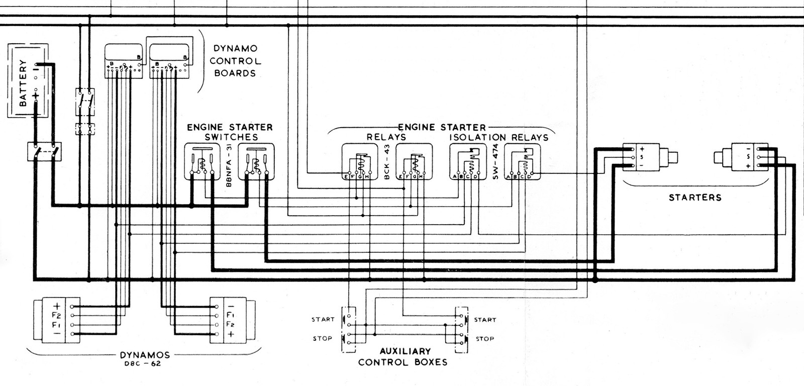
For the Derby Lightweights with the underframe mounted dynamos the schematic noted "engine starter relays are modified as shown on Plate 074 and also engine starter switches are deleted." Plate 074 is extracted below.
The second schematic is for the Met-Camm Lightweights.