Yellow Diamond Electrical Control System
Gear Controller
Gearbox and final drive controller
One was provided per cab.
Operation required a removable metal reversing lever. It is one of three items a driver required to bring to drive a 79xxx series DMU, the others being the vacuum brake handle and the lever for the train switch.
Description
From the BUT A Series Service Manual:
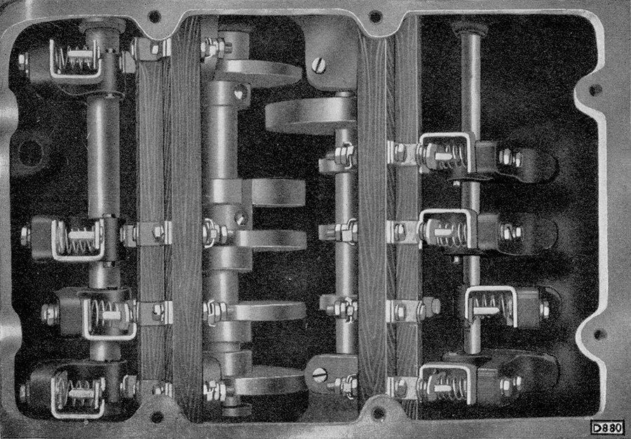
The gearbox controller is similar in construction to the throttle controller. There are two camshafts, one for the operation of the gears in the gearboxes and one to actuate the forward and reverse gears in the final drives. Each cam closes an electrical contact, thereby operating the appropriate electro-pneumatic valve, which in turn engages the selected gear.
When the forward and reverse lever is in the neutral position, it can be removed from the controller, thus rendering the car immobile.
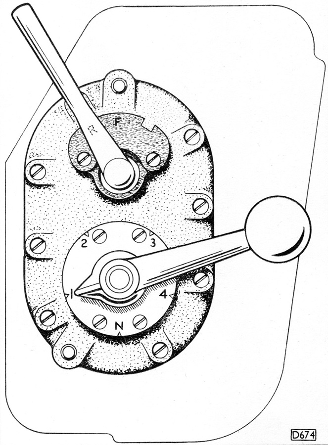
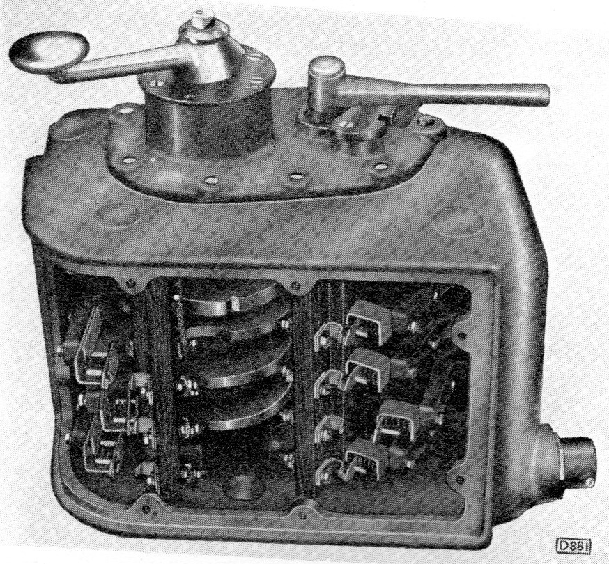
The next images show a plan view on which can be seen the handle positions for each gear — unlike the later Blue Square type the gear handle could be fully rotated — and a close up of the contacts.
Schematic
As shown in the BUT A series maintenance manual:
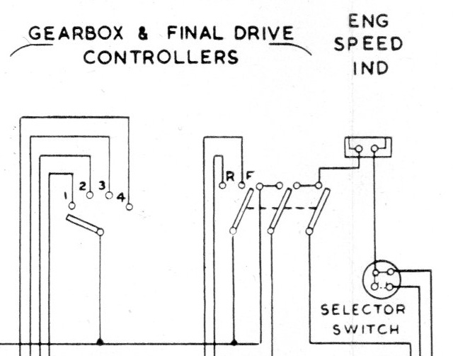
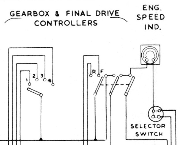
The first version is for the engine driven dynamo, the second the gearbox driven dynamo, the wiring of the gearbox controller is identical for both.
The direction controller makes three connections when the lever is inserted/operated. The middle one connects the train + circuit to several cab controls (gear, direction and throttle controllers and the individual engine start buttons on the control panel).
When the direction controller is placed in forward or reverse the + feed is connected to the Forward and Reverse circuits and onto the forward/reverse ep valves. On the jumper terminals both are 18, reverse on the no.1 side of the vehicle on both ends, forward on the no.2 side.
The gearbox controller will connect the + feeds to the Gear 1, 2, 3 or 4 circuits (11, 12, 13, 14 terminals on the jumpers) connected to the gear ep valves.
The third connection provides the common (rpm) feed to the engine speed indicator.
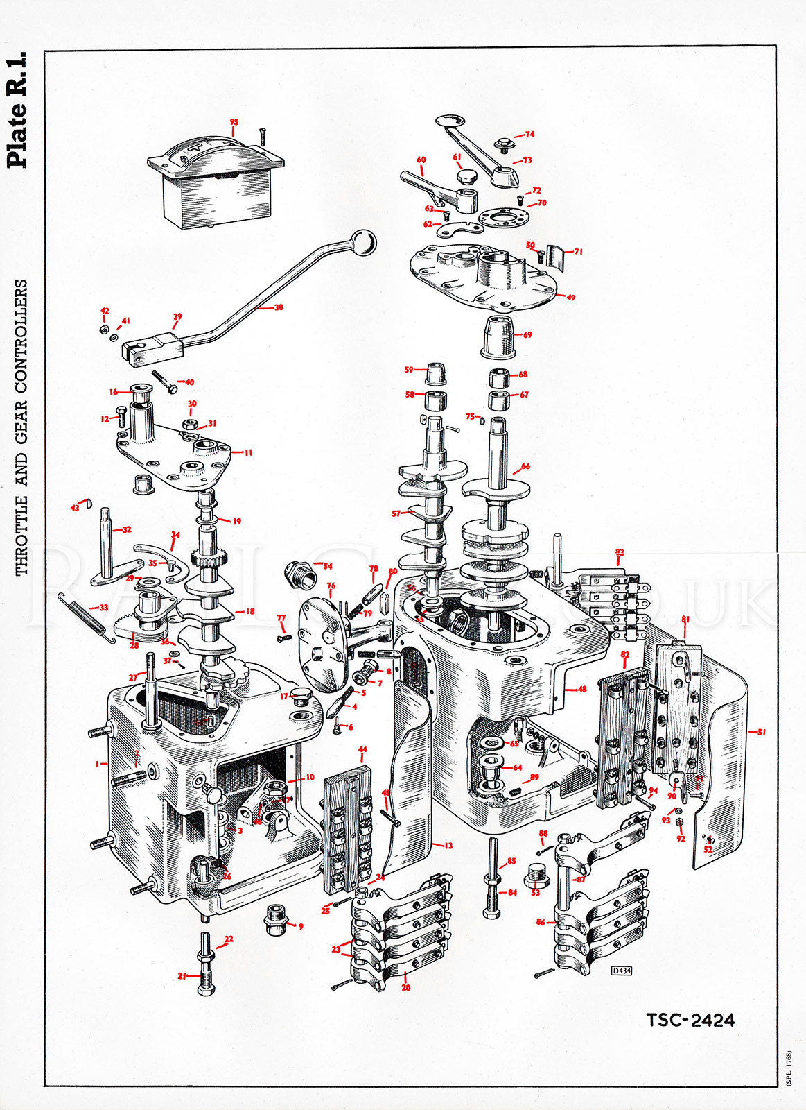
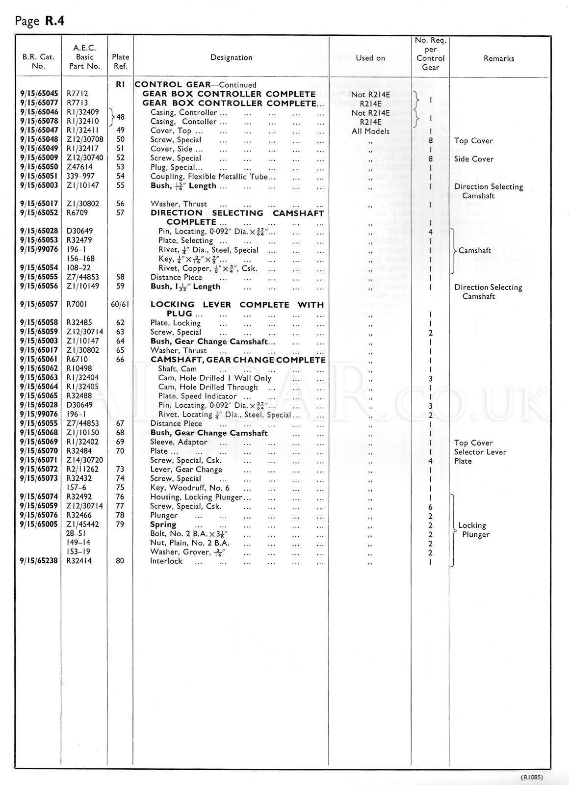
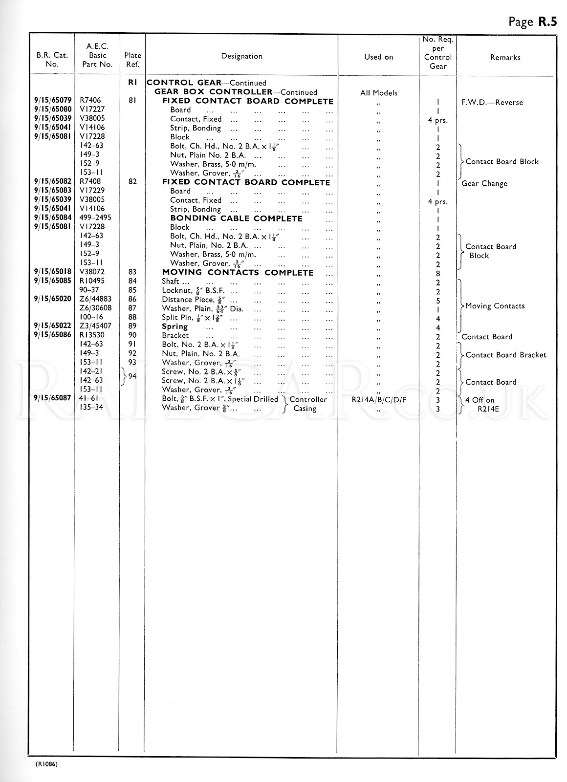
Exploded View
Taken from the AEC Spare Parts Catalogue.