Blue Square Electrical Control System
Throttle Controller
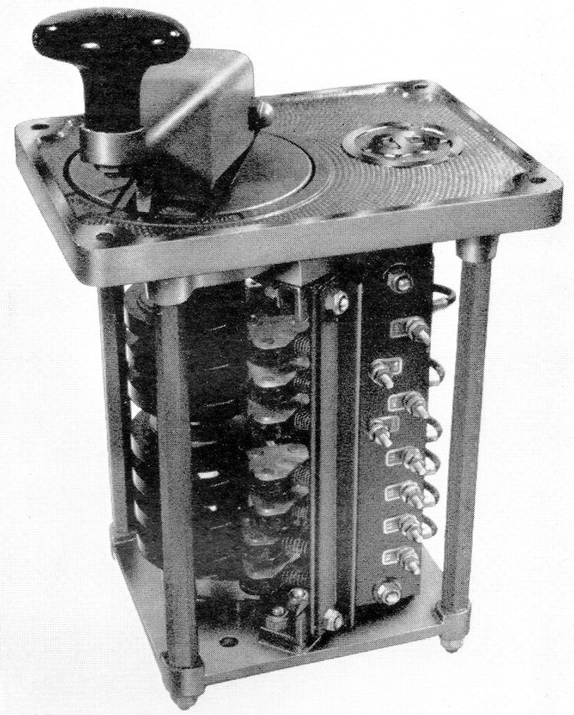
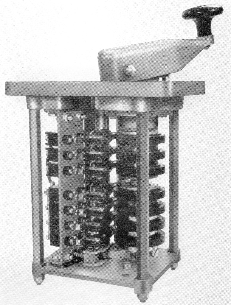
Combined Throttle Controller and "Deadman's Control"
This was fitted to Blue Square vehicles, it was comprised of components manufactured by Sharps Controls and supplied by B.U.T. as part of the control system. One was provided per cab, it would be to the drivers left side on the control desk.
Description
From the BUT 50000 Series Service Manual:
The throttle control lever is connected by linkage to a shaft which carries a number of cams. Each cam closes an electrical contact, when in the appropriate position (depending on the position of the control lever), which in turn operates the solenoid in the corresponding E.P. valve, thus actuating the throttle control motors.
The "deadman's" control valve consists mainly of a solenoid operated control valve, an emergency control valve and a timing chamber. The timing chamber is designed to allow a delay of approximately six seconds before the brakes are applied.
For details of the "deadman's" control valve see Gresham and Craven's handbook "Instructions for Gresham's Quick Release Vacuum Brake Equipment on British Railways Railcars."
Schematic
As shown in the BUT 50000 series manual:
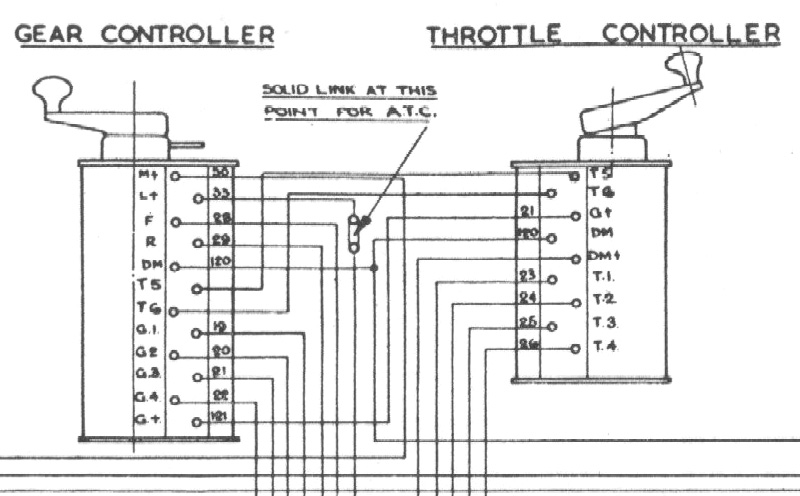
The top three connections (T5, T6 and G+) go direct to the gear controller.
The next two connections are for the deadman's control, DM is also connected to the gear controller but also goes to the "Deadman's Extension Button". DM+ goes to circuit 32 (as does the other connection to the extension button), which is the "Deadmans" wire that goes through all vehicles.
The final four connections are T1, T2, T3, T4, circuits 23-26, the Throttle 1-4 wires that go through all vehicles.
If the throttle is placed in, for example, position one then circuit 23 (Throttle 1) is energised throughout the whole train. On each power car the "EP Control Relay Panel" is connected to this circuit, on these the Throttle 1 Relay will be activated which will in turn activates the Throttle 1 EP Valve admitting compressed air that will put the throttle motor into the number 1 position.
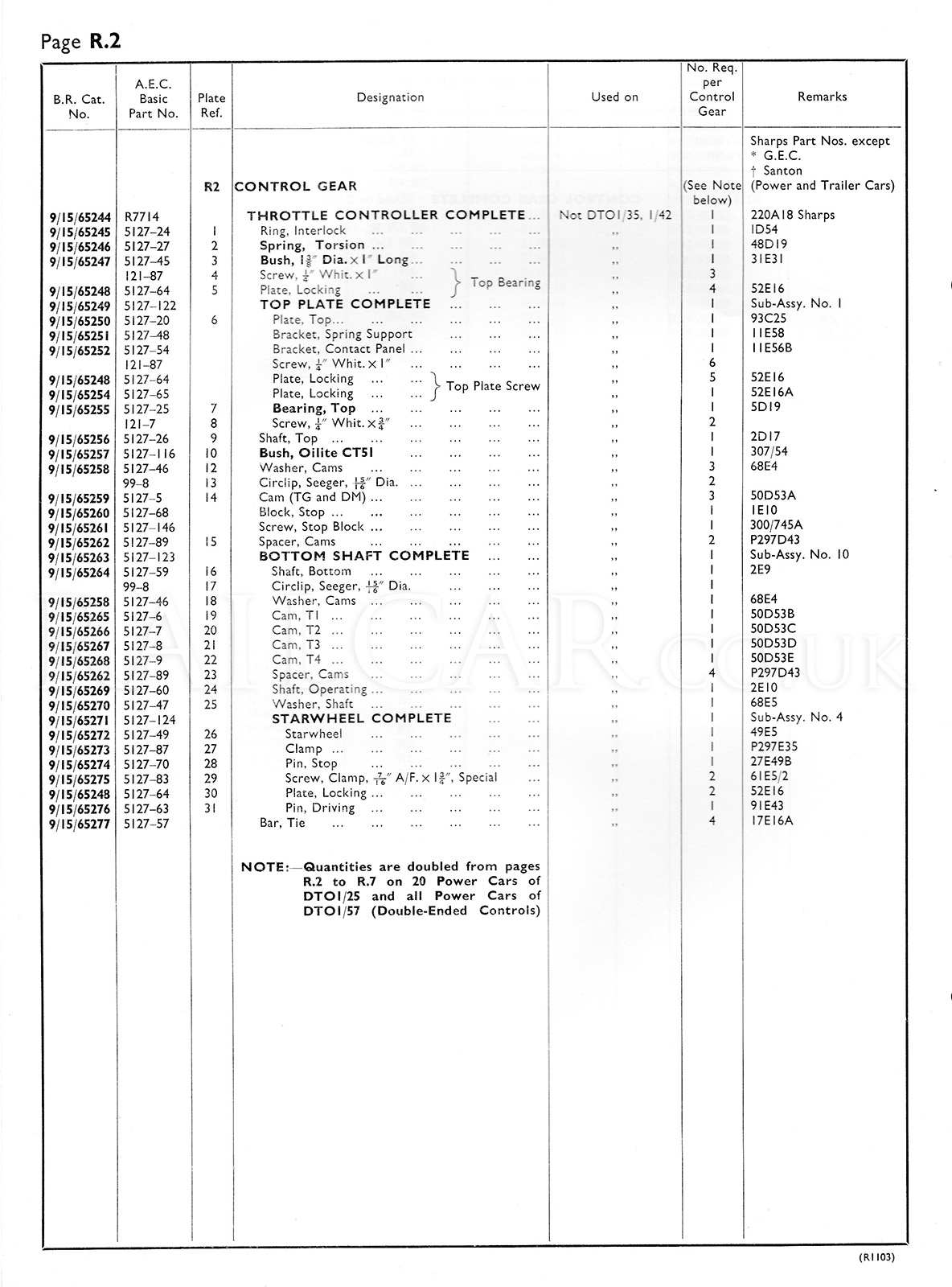
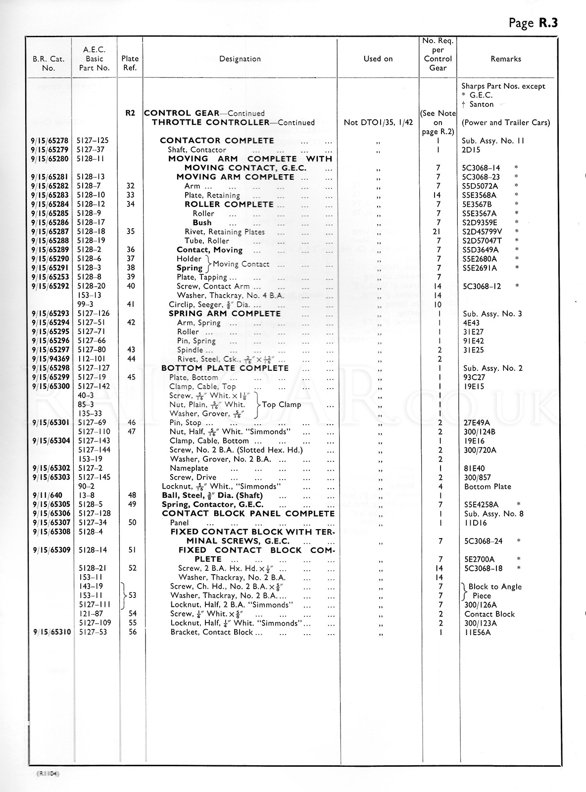
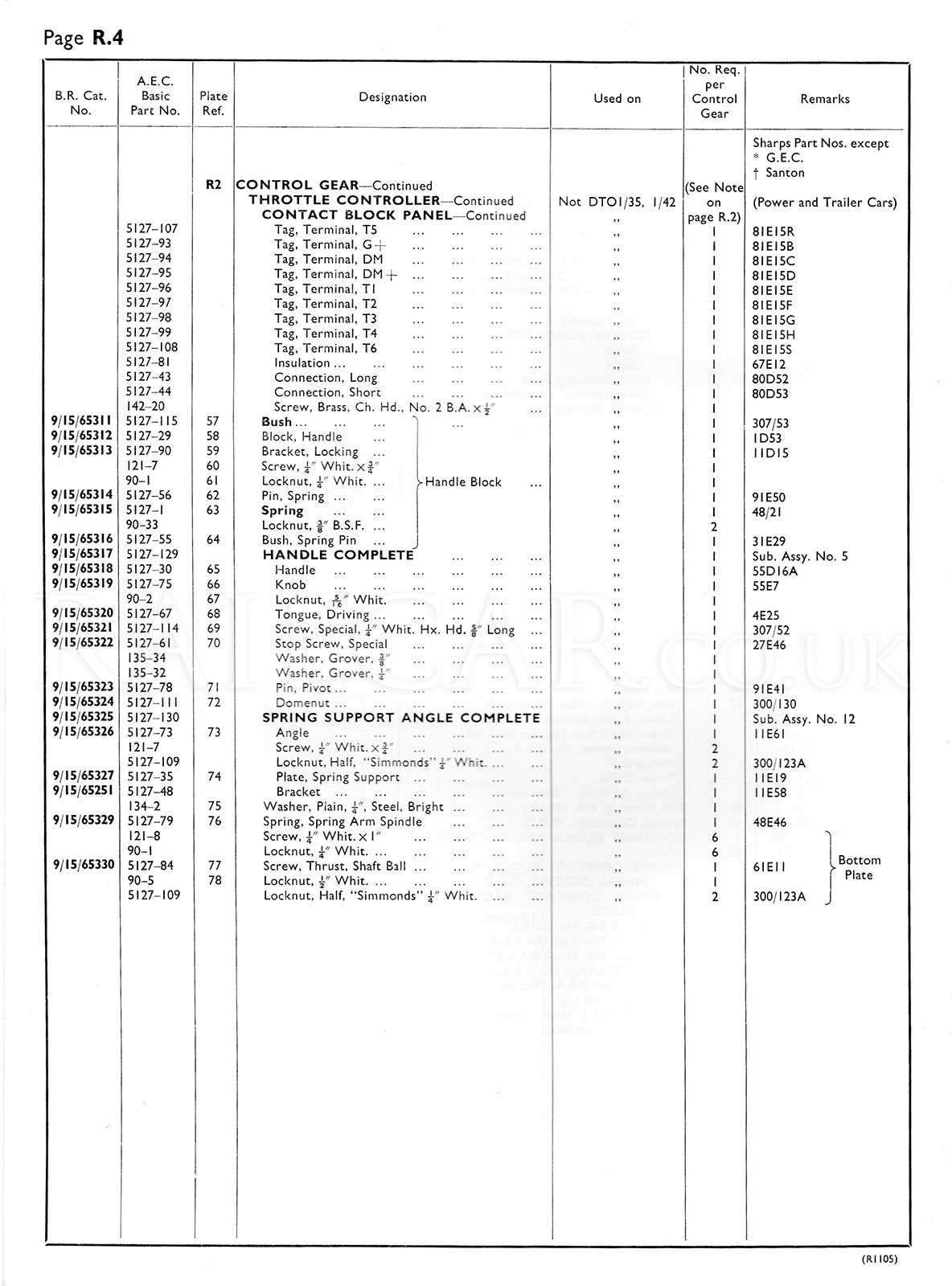
Exploded View
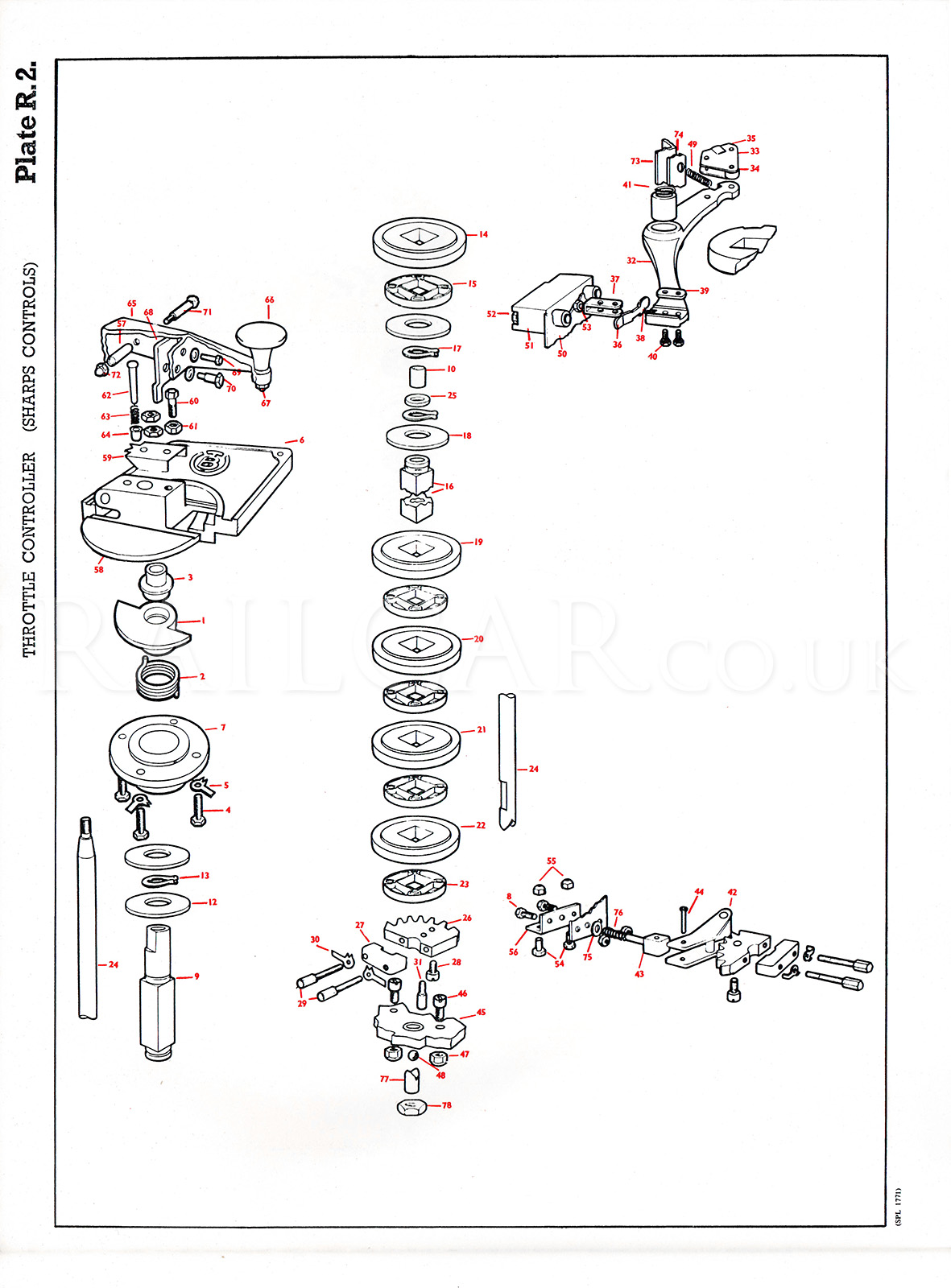
Taken from the AEC Spare Parts Catalogue.
The parts are identified in the three pages below, along with the AEC/BR/Sharps part numbers.