
Blue Square Electrical Control System
Engine Local Control Box
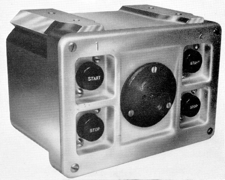
One was provided per engine located on the underframe. The outside was normally left in self-coloured allow, the plastic buttons were black with white lettering.
The left buttons are for the number one engine, the right buttons for the number two engine.It some point the start button was removed for the engine on the opposite side.
Some types, such as Class 108s, had a different shape of box with three buttons on a vertical strip.
Description
From the BUT 50000 Series Service Manual:
This unit is provided to facilitate starting or stopping the engine or engines from the side of the car.
It has two push button switches for starting and two for stopping the engines, and also an emergency lighting socket.
One control box is mounted adjacent to each engine.
Schematic
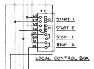
This shows the connections to the switches, taken from the BUT 50000 Series Service Manual. This is for the number one engine, number two is similar. The circuits used are:
- 27 Local Start 1
- 30 Local Start 2
- 33 Train +
- 51 Local +
- 60 Local Stop 1
- 61 Local Stop 2
The start switches have four connections, one pair connected when the button is not being pushed, and a pair that connect when it is.
The stop buttons simply connect the positive local feed (circuit 51) to the appropriate stop circuit when the button is pressed.