
Blue Square Electrical Control System
E.P. Control Relay Panel
One was provided per power car, located out of view in the cab.
Some early deliveries, such as Cravens units, only had an engine indicator light panel for four power cars, requiring a 12-way panel, later this was standardised to six power cars requiring an 18-way panel.
Description
From the BUT 50000 Series Service Manual:
The purpose of this unit is to isolate the engine lights and the air indicator lights in the trailing driving cabs.
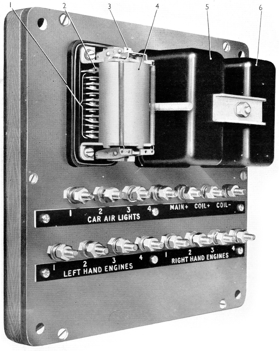
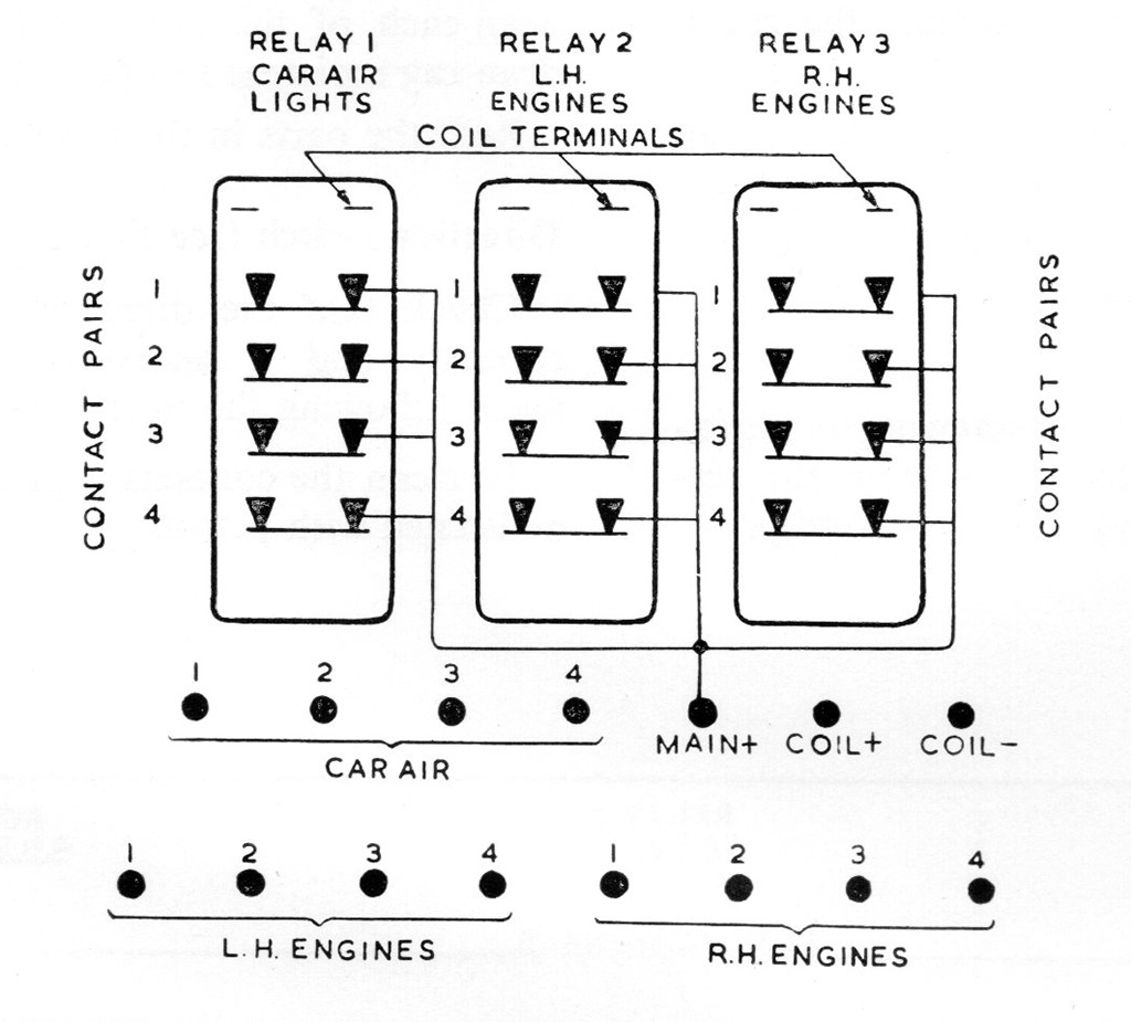
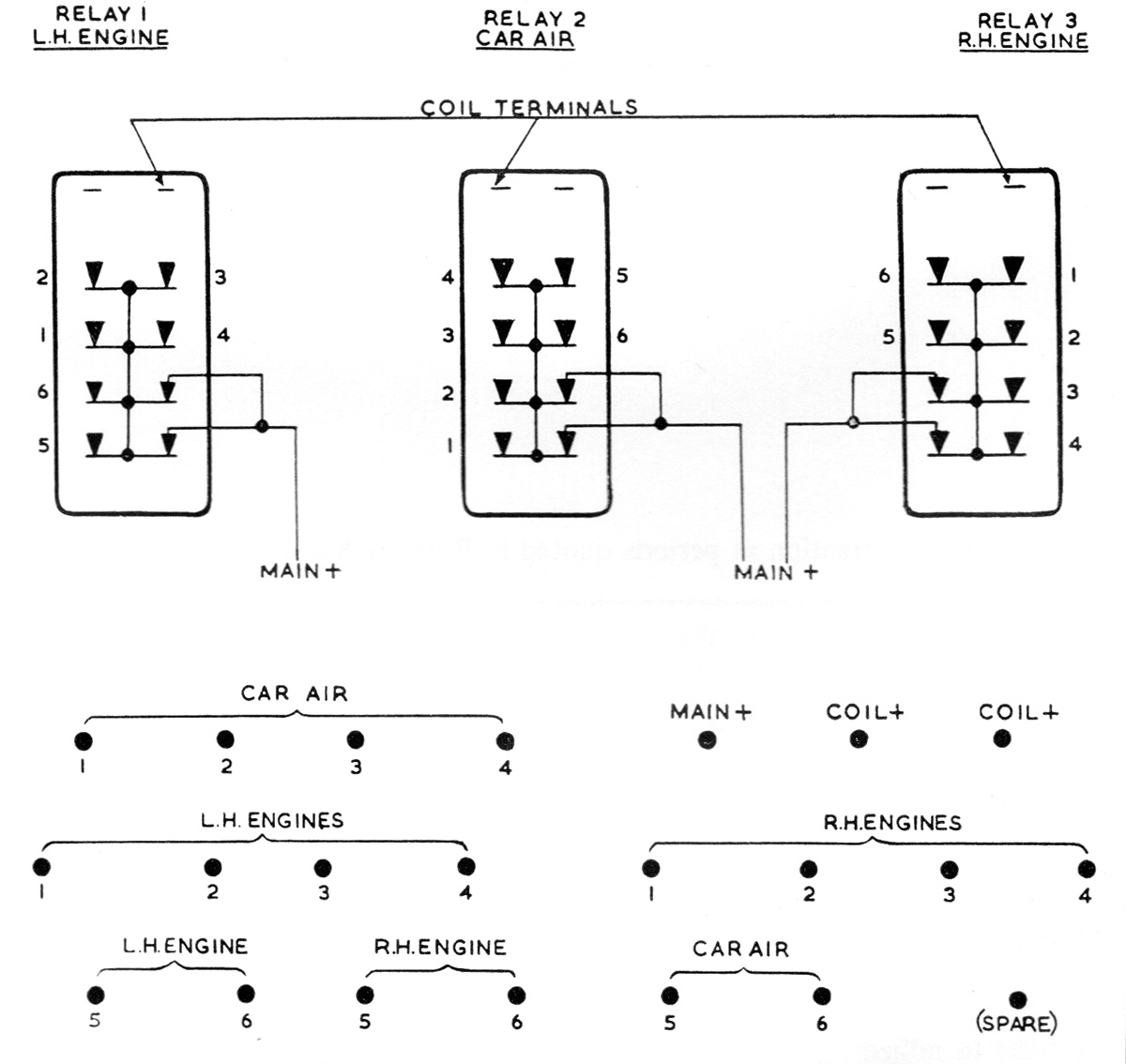
The unit consists of three relays mounted on a bakelight base. The relays are either four or six pole and are brought out to twelve or eighteen terminals below the relays.
Schematic
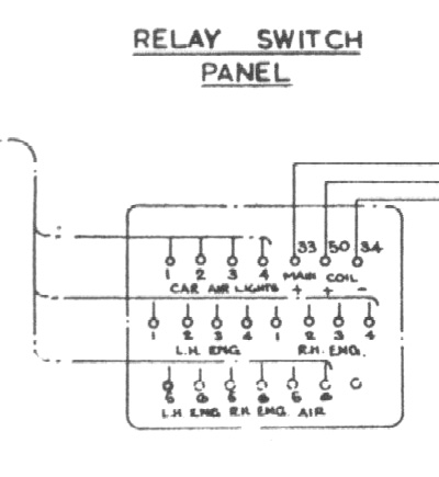
This shows the connections to the panel, taken from the BUT 50000 Series Service Manual.
The combined wiring to the left goes to the "Engine Control Panel".
Wires 33 and 34 are the "Train +" and "Train -" circuits that go through all vehicles.
Wire 50 comes from the Gear Controller, activated when the reversing lever is the forward or reverse position. This operates the coils, connecting all the indicator bulbs on the "Engine Control Panel" to the "Train +" circuit.