
Blue Square Electrical Control System
Oil Pressure Switch
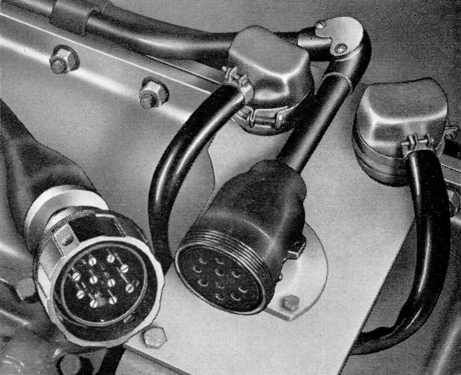
Two oil pressure switches were fitted to each engine, they can be seen on either side of the conduit leading to the socket. They had rubber caps protecting the connections underneath.
Description
From the BUT 50000 Series Service Manual:
A double pole switch in the form of two standard single pole units is mounted on the engine casing extension. One pole operates the oil pressure warning lights on the driver's control panel and the other, in the event of low oil pressure, operated the engine shut-down solenoid.
Each switch consists of a diaphragm and electrical contacts enclosed in a sealed casing.
Oil pressure on the diaphragm causes the contacts to close, thus completing the electrical circuit to the indicator lights or the engine shut-down solenoid.
Schematic
The schematic shows the electrical connections to the components fitted to the engines, as shown in the BUT 50000 series manual. Number one engine is on the left, number two on the right, both are connected via the "Engine Plug and Socket" connection.
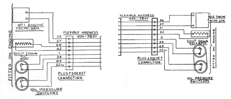
One switch was connection to the "Train -" circuit (wire 34) and either the "Oil Indicator 1" circuit (wire 1) for engine one, or the "Oil Indicator 2" circuit (wire 2) for engine two. These two wires, which went to all vehicles in the formation, would operate the "Oil Indication Lamp" on the "Engine Control Panel" in the cab that was being used.
The other switch was connected to the "Local -" circuit (wire 52W via the "Water Level Switch") and wire 64 (engine one) or wire 65 (engine two) on the "Engine Control Relay Panel". In the event of this train negative feed not reaching this control panel, either because of low oil pressure or low water causing the switches to open, the control panel would operate the stop solenoid for that engine.