
Blue Square Electrical Control System
Engine Shut-Down Solenoid
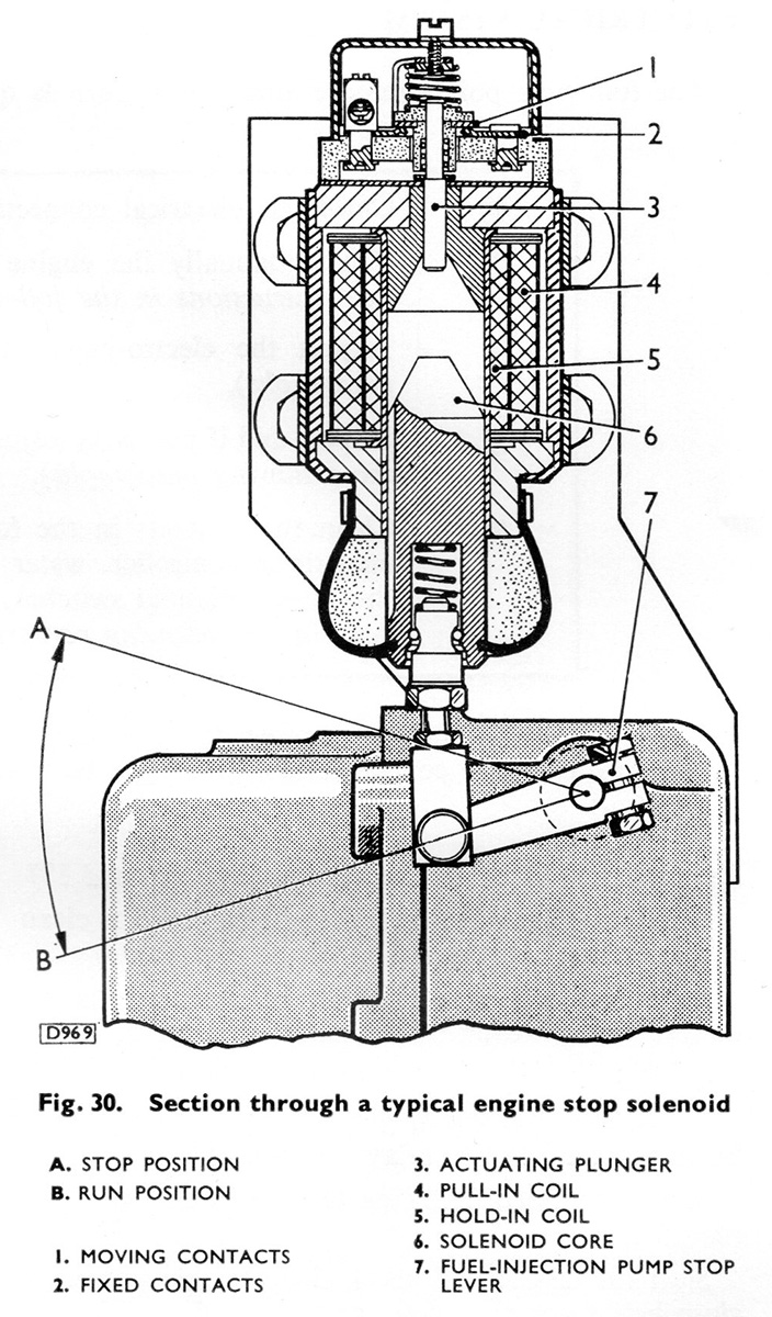
Description
From the BUT 50000 Series Service Manual:
The shut-down solenoid is mounted on a bracket attached to the fuel-injection pump, and when energised cuts off the supply of fuel to the engine.
This unit is continuously rated and consists of a "pull-in" coil and a "hold-in" coil in which a solenoid core is free to move.
On energising the "pull-in" coil the solenoid core rises against the actuating plunger and breaks the moving contact. This action brings into circuit the "hold-in" coil, which has a low current consumption and is designed to hold the solenoid in the stop position.
Schematic
The schematic shows the electrical connections to the components fitted to the engines, as shown in the BUT 50000 series manual. Number one engine is on the left, number two on the right, both are connected via the "Engine Plug and Socket" connection.
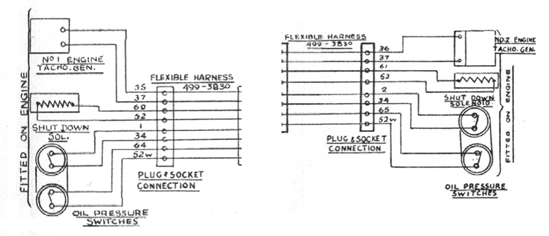
The solenoids are connected to circuit 52, the "Local -", and either wire 60 (on engine one) - the "Local Stop 1" circuit, or wire 61 (on engine two) - the "Local Stop 2" circuit.
These two local stop circuits provide the positive feed from a variety of components such as the "Engine Local Control Box" beside the engines when the engine stop buttons are pressed; the "Fire Alarm Control Panel" in the event of overheating being detected; or the "Engine Control Relay Panel". The later can be triggered by a number of other actions such as the engine stop button being pressed on the "Engine Control Panel" in any cab on the train, or the oil pressure or water level switches.