
Blue Square Electrical Control System
Direction Switch
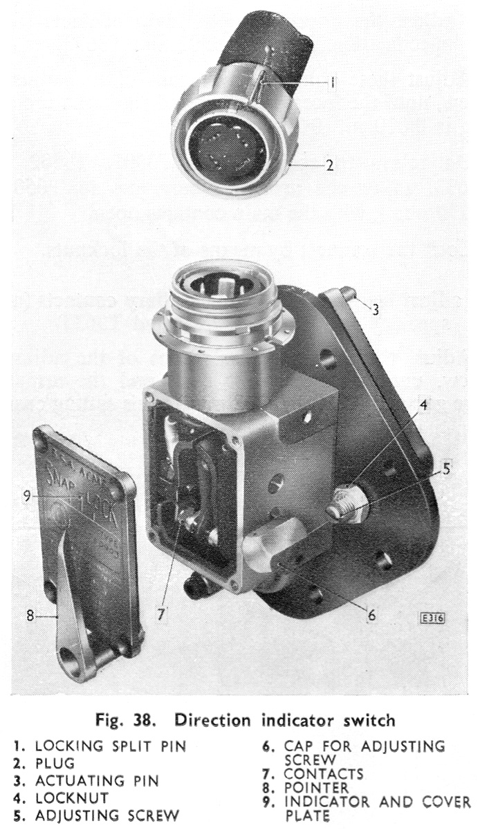
The switch cover noted this was a "Snap-Lock" type. One was fitted to each final drive, connected via a flexible harness.
Description
From the BUT 50000 Series Service Manual:
A direction switch is mounted on each final drive casing.
This unit is a single pole change over switch operated by actuation of the striking lever in the final drive unit.
It indicates electronically, by means of a light on the driver's control panel, whether the final drive is properly engaged (see also "Air pressure switches" in this Section).
Schematic
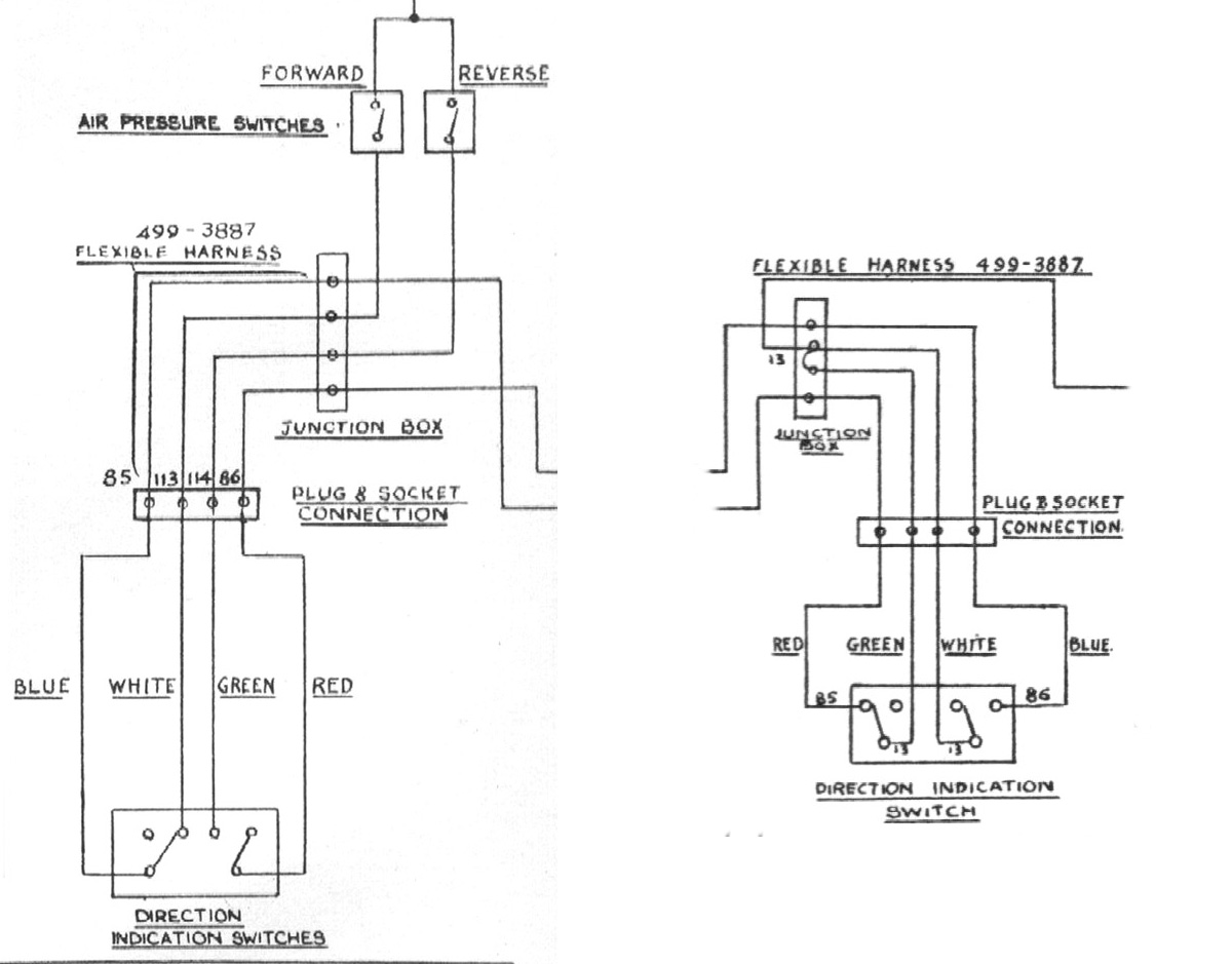
This shows the connections to the switches, taken from the BUT 50000 Series Service Manual. I've show the two switches side by side, but they would be at opposite ends of the vehicle.
The feed to the number one switch is via the "Air Pressure Switches" which connects the "Train –" (circuit 34) to wires 113 and 114 when there is sufficient air pressure.
If both final drives are in the same direction then connections are made (via wires 85/6) with wire 13 at the number two final drive. This is the "Air Indicator 1" circuit and is responsible for lighting the "Air/Axle" lamp on the "Engine Control Panel" in the cab.