
AC Cars Railbus
Underframe to body suspension
The body suspension adopted by AC Cars was of the utmost simplicity. Four interweaved rubber-bonded-to-metal springs were used, one at each corner of the underframe. These springs, which were of the type employed for Metalastik bolster suspension, were set so that the resultant forces were focused at or near the centre of gravity of the body. This arrangement reduced roll and any tendency of the body to dip on braking and permitted the springs to be loaded in shear and compression - the best combination for safety, load/deflection characteristics and long service.
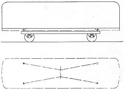
The diagram showing the resultant forces of the body suspension springs.
The ratio of shear to compression loading varied according to the direction of the load. Transversely the springs, which had an inward rake of 10 degrees, were largely in shear. The compression element was higher in the vertical plane, as the springs were tilted upwards at an angle of 16 degrees. In for-and-aft directions, where the greatest stiffness was required, the springs were almost entirely in compression.
Angular settings and rubber hardness were selected to give a static deflection of 2.66 in. under the full load of 19,200 lb. This deflection was considered the most suitable for a light, four-wheel railbus operating on branch lines. Metalastik Springaid buffers attached to the underframe limited the vertical deflection in the event of overloading, and excessive movement due to heavy side loads when traversing cross-overs was also checked by Metalastik buffers. Hydraulic dampers were fitted.
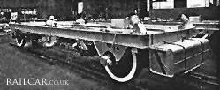
In the image of the underframe note the rubber bonded metal-to-metal springs sticking up at each corner.