
Class 112/3 Cravens 2-car DMUs
Description
Construction
Body rails were formed from 1/8 in Corten steel, with 1/8 in mild steel pillars, 16 swg steel bodyside panels and 16 swg galvanised steel roof. Limpet asbestos supplied by J. W. Roberts Ltd. and Cape Asbestos was sprayed to the inside of the roof, bodysides and ends. The floor was corrugated Corten steel sheets, with mineral wool to provide sound and heat insulation, and covered by 1/2 inch multiply. On top of this was 1/2 inch Sundela board and then the linoleum / carpet.
Underframes were built up from rolled and pressed steel section, with Oleo pneumatic buffers. Standard BR pattern bogies with Timken roller-bearing axleboxes were used, with laminated springs supplied by William Griffiths Ltd. and Steel, Peech & Tozer Ltd. and coil springs from Turton Bros & Matthews Ltd.
Engines
These were an eight cylinder model of type C8NFLH, developing 238hp at 1,880rpm. They had a direct injection single bank monobloc unit of 5 1/8 inch bore and 6in stroke. Engine auxiliaries were accessible from the side, and the two large oil bath air cleaners were frame mounted. A heat exchanger was fitted for temperature control of the lub oil. The exhauster manifolds were water cooled, and the engine was mounted on Metalastik compression mountings at the front end and Metalastik shear mountings at the rear. Torque reaction buffer stops were fitted. The standard range of engine protection and Graviner automatic fire protection was installed.

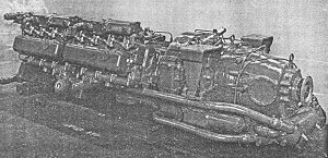
The Rolls-Royce engine with the Twin-Disc torque converter on the left hand side. Prominent on this side of the engine is the fuel pump, with four flexible air lines coming from pipes behind the solebar to the throttle motor at the bottom of the fuel pump - each pipe corresponding to a position on the drivers throttle controller in the cab.
At the free end of the engine was a short cardan shaft to a power take off box, which drove the CAV alternator and Clayton exhauster through multi V belts. At the output end of the power take of was a cardan shaft drive to a spiral-bevel right angle gearbox. This provided a shaft drive to the 29 inch diameter fan, a belt drive to a second exhauster, and a gear drive to a Westinghouse E15 compressor. The Coventry radiator was suspended on Metacone mountings, had a headertank installed under the passenger seating. The cooling system was not pressurised.
The gross weight of a set with all seats occupied was approximately 70 tons, giving 6.8hp per ton. Empty it was 8.1hp/ton, which compared favourably with 5.7hp/ton that the Cravens power/trailer had.
Mechanical Transmission (Class 112 only)
From the engine there was a freewheel, 4-speed gearbox (secured by a 3-point suspension), then cardan shaft to the axle-mounted final drive.
Hydraulic Transmission (Class 113 only)
The Rolls Royce Twin Disc three-stage torque converter type DFR 10,000 had a stall/torque ratio of 4.3:1 at 1,500 input rpm. An automatic converter lock-out and double freewheel assembly was fitted. When the converter was isolated, direct drive was taken through a multi-plate clutch and an inner shaft to the output flange. A freewheel was incorporated into the drive to allow coasting. It was claimed that the fitting of the freewheel reduced fuel consumption, and by allowing changeover from converter to direct-drive to be made with the engines idling, a very smooth change was made with minimum wear on the clutch plates. Engine damage resulting from over-speed on down gradients was eliminated and a safety disconnection was provided by the freewheel in the event of engine failure or seizure.
The drive to the converter was through a multi-plate clutch. A freewheel on the output side of the converter allowed the converter to stop when the car was running in direct drive. Both clutches were engaged by loading of the pressure plates by oil from a continuously running pump. Diesel oil, supplied direct from the main tank was used for the working fluid of the converter. Cooling of the oil was by a heat-exchanger incorporated in the engine coolant circuit.
The converter unit was flange mounted to the engine, and the drive from the output coupling to the SCG RF28 final drive on the axle was by torsionally flexible cardan shaft. This was developed by Rolls Royce for railcar transmissions, and consisted of a silicon manganese steel torsion bar enclosed in a normal type cardan shaft tube. When running in direct drive the torque was transmitted by the torsion bar, the torsional vibration being dampened by a disc type viscous damper incorporated in one universal joint. In the higher torque range, when the converter was in operation, excessive twisting of the shaft was limited by stops and the drive was then take through the outer tube in the normal manner.
The change from converter to direct drive was made automatically at about 46mph. At this speed a voltage was passed by the speedo-generator to the relays of a Smith-Stone lock-out box. During the transition from converter to direct drive the engines are automatically returned to idling and then speeded up to the appropriate speed for direct drive at the rail speed. When the train's speed fell, the converter drive was automatically re-engaged at 39 mph, without the engine speed dropping, but increased to that required for operation of the torque converter.
Final drive gear engagement was selected for the required direction by air operated dog-clutches. Power could not be applied until the dogs were fully engaged. If the dogs were in the wrong position for engagement an automatic local circuit was brought into operation when the driver depressed his deadmans handle. This applied sufficient drag torque to enable the dog teeth to engage, while holding the engine at idling speed. When the dogs had moved into correct mesh, the drag was removed and the engine permitted to increase speed.
Compressed air for control operation was provided by one 15 cu/ft per minute compressor on each car, mounted on the auxiliary gearbox. The nominal control air pressure varied between 75 and 95 lb per square inch. The controls could be operated down to 50lb per sq in, when a safety interlock cut in and the air and axle light extinguished below this figure.
Interior
As on other Cravens cars, the exhaust systems rose through the interior of the cars, on the DMBS through a trunk in the guards van, and in the DMC through a trunk on the outside of the toilet. With only one engine, there was only a single exhaust on each car. Loudaphone equipment was provided for driver-guard communication. Cab windows had Laycock pneumatic wipers. On the Class 113s the cab roof dome incorporated a combined four digit route and destination indicator which distinguished these sets from other Cravens cars. The cab ceiling was moulded from resin-bonded fibre glass.

The driver's compartment of mechanical DMBS M51684 with standard BUT 'Sharps' controls.
In the hydraulic cars the drivers controls consisted of the throttle, incorporating the deadmans device, and was marked for either idling, 1, 2, 3 or 4, a drive selector handle for obtaining drive, or gears 1 to 4 for when coupled to gearbox cars, and a detachable reversing lever. All controls were EP operated. The fuel pump racks were controlled by an all speed CAV governor, which in turn was loaded by a pneumatic activator. An air choke in the supply line gave a time delay to smooth out any jerky operation of the controller.
When a set hydraulic sets was coupled to a gearbox set the controller had to be operated as for the mechanical drives. To aid this, the speedometer dial was marked in segments corresponding to gear change positions to indicate to the driver when to change gear.
Tubular seat frames with curved tops supplied by G. D. Peters Ltd. had foam rubber cushions and squabs with moquette covering and vynide trim, supplied by J. Holdsworth Ltd., TF Firth & Sons Ltd. and Imperial Chemical Industries Ltd. Partitions were fully glazed down to waist level. Second class had cut moquette trimmed with brown vynide and white piping. Parcel racks were tubular anodised aluminium mounted on aluminium brackets. The Beclawat bodyside windows were framed in aluminium-alloy mouldings without window pans, and bonded in Prestik. The sliding ventilator units were supplied by J. Gibbons Ltd.
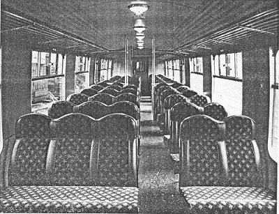
Ceiling panels were 1/8 inch thick Laconite hardboard. Bodyside panels in second class saloons were opaline green matt, and dove grey in first class. The plastic panels were supplied by Formica Ltd. and Warerite Ltd. Finishings were mahogany, and the linoleum was green marble in vestibules and second class saloons, and a grey speckled carpet in the first class saloon. Blockboard and plywood panels were supplied by Edmonton Panel Co. and Insulation Equipment Ltd.
Each car had two underframe Smiths Mark III combustion heaters which fed the warm air to the saloons via bodyside grilles under the seats. Air-Vac roof vents provided ventilation via dust arresters.
The DMBS had two passenger saloons, the one behind the cab had 19 no-smoking seats, accessed through a sliding door. The centre saloon had no doors on the bulkhead to separate the saloon from the vestibule. The guards van had a wire mesh grille allowing passengers to pass through but providing security for luggage / parcels, which could be up to 1.5 tons (evenly distributed of course!).
Alterations
By August 1969, mainly due to the incident at Sandridge, the main fuel tanks on the remaining nine Class 112 sets were repositioned to near the non-powered bogie, rather than sadling the cardan shaft. Also as a result of this incident, lower stepboards were added to one door on each sie, and additional communication chain points were added, previously there were none of these in the passenger saloons.