
Class 100 Gloucester RC&W 2-car DMUs
Construction
The main consideration during design was saving weight to obtain good acceleration, and robust construction to give a long working life. The integral type body structure was assembled from welded units, considered the most suitable as this used methods within the scope of existing railway carriage workshop equipment and techniques. Closed or tubular sections were used to take advantage of their superior elastic stability and torsional resistance. This arrangement gave them a distinctive "pinched in" smooth lower bodyside arrangement, with no visible underframe.
Basic Structural Design
Weight saving is always desirable with rail vehicles; but the British Railways C1 loading gauge, with its constriction at platform level and maximum width a little higher at seat level posed problems when considering a really satisfactory design of integral framing. An integral type of frame structure made up from welded units - sub-assemblies such as body sides, ends, floor roof and so on, was thought to be the solution to these problems, and a box girder made up largely of tubular sections was seen by the designers as having advantages, particularly as during the life of a vehicle most frame members are called upon to act as struts, for which tubular sections have superior stability and resistance to torsion. The result was a body shell with a weight of just 21% of the completed railcar empty weight, and in the case of the driving trailer 26 per cent.
| Power Car | t. | c. | q. | lb. |
|---|---|---|---|---|
| Body Shell | 6 | 7 | 3 | 0 |
| Engines and other equipment | 3 | 5 | 0 | 17 |
| Other equipment and general interior finish | 9 | 4 | 0 | 5 |
| Fuel and water | - | 7 | 0 | 16 |
| Bogies : driving | 5 | 11 | 0 | 10 |
| trailing | 5 | 9 | 3 | 8 |
| Total weight of Railcar | 30 | 5 | 0 | 0 |
| Driving Trailer | t. | c. | q. | lb. |
| Body Shell | 6 | 7 | 3 | 0 |
| Other equipment and general interior finish | 8 | 8 | 0 | 18 |
| Heater fuel and water | - | 5 | 1 | 0 |
| Bogies : with dynamo | 4 | 19 | 3 | 0 |
| without dynamo | 4 | 14 | 0 | 10 |
| Total weight of control trailer | 24 | 15 | 0 | 0 |
An empty set weighed 55 tons, and fully laden would be approx. 66 tons with a seating capacity of 118, the weight per seat was 1,035lb, and hp per ton of empty weight was 5.45, and 4.6 hp per ton when fully laden.
Body Sides
In an integral body of this type it is important that the vertical loads due to the weight of the structure, equipment and passengers should be distributed into, and reacted by, the whole depth of the body side including the solebars. Structurally a flat or slab body side is the ideal truss. The loading gauge excluded this possibility, since the width over panels is 9 ft. but the maximum width over solebars is limited to about 7 ft. 11 in. The problem was further complicated because the change in width from 9ft. to 7 ft. 11 in. is not gradual, but takes place almost entirely at floor level.
The transfer of load from solebars in the body side was effectively achieved by bending the pillars sharply at floor level; the pillar was actually built into the sole-bar to ensure efficient transfer of load without giving rise to sudden stress changes. Calculations showed that the forces in the pillars were at a maximum around floor level, and determined the size of pillar sections in this area. At the cantrail this size of pillar section was greater than necessary, and advantage was taken of the weight saving made possible by using a tube whose wall thickness varied. Such tubes - known as butted tubes - were readily drawn commercially being commonly used in bus seat side bends and steering columns of bicycles. The tubular pillars incorporated in this coach structure were of constant thickness over the bottom 18 inches, and the wall thickness then tapered over a length of 12 inches. Thereafter the thickness remained constant at the thinner gauge up to cantrail level. The use of this bent butted tube, for the body side pillar overcame the loading gauge problem at solebar level and it saved weight and enhanced the stability and efficiency of the body side by permitting a good pillar attachment.

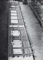
For efficient use of metal, compressive strength and stability, a double tube was chosen to form the basis of a fabricated solebar. These solebars were built up by welding as units, as shown in the first picture. The pillars were riveted to the solebars.
A stiff, deep box section was required to form the cantrail, and this was fabricated from cold formed sections generally in Corten steel. Considerable attention was paid to the connection of piIlar to cantrail since this connection was required to transfer shear into the cantraiI. This design provided a truly integral truss and without making a displeasing outside appearance. The framing members were joined by welding, with panels also attached by welding to form a unit.
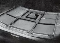
The second image shows the sub-assembly of one side being assembled on a jig.
Floor and Roof

There was no separate underframe in the normal sense, but the weight of metal usually concentrated in the center longitudinals was spread over the whole width of the floor in the form of corrugated steel sections with the corrugations running longitudinally. This corrugated steel floor was cold rolled in 57 ft. lengths to eliminate the difficulty of matching and welding up joints across the coach, to sustain both the buffing and draw loads and to support passenger load between crossbars. The frame bolster, headstocks and buffing gear supporting structures were built up as unit assemblies. Again for the purposes of weight and strength, these units were fabricated from steel tube, sheet and plate, permitting the metal to be concentrated where it would do most work. Diffusion of buffing and draw loads into the corrugated steel floor was achieved by incorporating tubular longitudinals immediately behind the buffing and drawgear. In order to assist the diffusion of end loads into the corrugated floor, and to save weight, these tubular longitudinals were tapered in wall thickness, the thickness being greater at the two headstocks at the ends.
The first image shows the longitudinal corrugated steel sections forming the underframe.
The body end and the roof between cantrails were built up in much the same way as the standard British Railways coaches. With regard to the roof, it was felt that shear lag across the roof panels would reduce the effectiveness or incorporating extra framing or purlins, and therefore the cantrails were considered as the main load carrying members.
The second image shows a sub-assembly being formed in a jig.
The various components comprising the whole of the structure were assembled to form a complete unit by a combination of riveting and welding designed to facilitate repairs being carried out on the frame without difficulty.
Many firms supplied the different metals required. The cold formed sections came from Metal Sections Ltd., and the Corten body panels from the Steel Co. of Wales Ltd. John Summers Ltd. supplied the roof sheets, and Deans & Sons (Yorkshire) Ltd. supplied the Cast Alloy doors.
Strength Testing
In order to prove that the design satisfied the British Transport Commission strength requirements it was decided to test the coach body shell, using electrical resistance strain gauges to determine stress levels at selected points. For this purpose a shell was taken out of the production line and set up in such a way as to represent the actual conditions of body support which existed in service, and a special testing rig was erected for the purpose of applying a compression load to the side buffers.
With reference to the stress analysis of the coach 200 positions around the structure were selected for stress measurement. For applied vertical loads, theoretical analysis indicated that the most severely stressed regions would be in the solebar adjacent to the body bolster, the body bolster itself, the quarter, cantrails and solebars framing one of the doors between bogie centres. Additional gauges were located across the floor and roof midway between bogie centres, and at the door openings mentioned above. Gauges were also applied to the quarter immediately above the bolster, since it was desired to ascertain the force distribution in this region of the coach.
Under an end buffing load, the most highly stressed parts indicated by theory were the solebars, the tubular longitudinals immediately behind the side buffers and those supporting the centre couplers, and the horizontal beam between the lower solebar tubes immediately behind the headstock. As it was also desired to study the behaviour of the corrugated floor under buffing load, gauges were located on this floor in such a way as to ascertain both the stress distribution across the floor, and the load diffusion into the floor from the butted tubular longitudinals.
The vertical load was applied by iron bars laid in the coach to represent a distributed passenger load. The end buffing load was applied by means of a hydraulic ram at the driving end of the coach, acting on an equalising beam which in turn acted on the side buffers. Another beam on rollers was held against the buffers at the non-driving end of the coach by means of a total of four circular-section tie bars running the length of the coach and reacting the ram thrust of the driving end. A series of strain gauges was attached to these tie bars to measure the force exerted by the ram, which was also checked by pressure gauge.
The test programme included the following loadings:
(a) A uniformly distributed load of 17 1/2 tons, 15 tons of which was applied and removed a minimum of five times during the course of the test programme.
(b) An end buffing load of 80 tons which was applied and removed a minimum of five times during the course of the tests, a uniformly distributed load of 2 1/2 tons remaining in the coach as a settling vertical load the whole time.
(c) A combination of the above, i.e., a total uniformly distributed load of 17 1/2 tons together with an 80-ton buffing load. This combination was applied once.
In order to ensure absolute reliability of the test results, it was necessary to work the structure for a number of cycles by applying and removing the maximum vertical and buffing loads several times. After such working of the structure the strain readings were not only linear (except for a very few lightly loaded points) but were consistent with each repeat of test. For each case (a) and (b) above, the test proper was carried out three times, a complete set of strain readings being taken at various load increments during each test run.
In a general way the tests showed that the attention paid to the joints of pillars to solebars and cantrail, together with the use of butted tubular pillars, was justified, since the vertical deflection of the coach at the solebars, midway between bogie centres, under a load of 15 tons, was only 0.13 in., and the inward movement of the body sides at the waist rail of the bolster quarter, door quarter, and single pillar at the coach centre line was 0.0312 in., 0.0548 in., and 0.101 in. respectively. These figures combined to show that the applied loads were reacted by the whole depth of the body side without distortion of the coach cross sections. Further, the stresses recorded in the pillars did not show any sudden change of stress level around the bend at the solebar.
The gauges located on the corrugated floor and the buffing gear support structure showed that the butted tubular longitudinals immediately behind the buffers diffused the end load into the whole width of the floor very efficiently. By the centre-line of the bolster the compressive stress level approached a more or less uniform value over the whole width of floor.
The applications of the combined vertical load and 80-ton buffing load caused the coach to contract elastically 0.46 inch over its length and no part of the structure suffered any permanent set.