
Charging Systems
Alternator Maintenance
By John Joyce
Batteries and charging systems are things that are taken for granted, until one morning your engines won't turn over because the batteries are flat. A little preventative maintenance pays reliability dividends in the long term. Here I present my suggestions as to maintenance and basic fault finding, based on several years' experience with DMUs and Mk 1 coaches - however as always I am open to corrections, suggestions and additions. This isn't intended to be an exhaustive or definitive guide; if in doubt, consult a specialist. I am happy to try to help with problems!
Introduction
Two basic charging systems are fitted: alternators to most power cars, and dynamos/generators to the remaining power cars and virtually all trailers. Engine-driven alternators, correctly maintained, should keep batteries in a good state for many years providing that each power car is run a couple of days each month.
Tools
A digital voltmeter is cheap, robust and reliable; analogue ones tend to take exception to being thrown around in toolboxes! Beware of using 'megger' type resistance meters; semiconductors are easily damaged by the high voltages generated by these. Beyond that, the contents of an average toolbox is all that is required: screwdrivers and spanners.
Alternators
Alternators make a huge difference to the reliability of DMU vehicles, eliminating the need for external charging unless a car is stood for months out of use. Maintenance is minimal, consisting of checking charging voltage and brushgear condition. There are two basic types that I am aware of, the earlier AC8 (and derivative AC8A) which are long obsolete in terms of manufacture but still in widespread use, and the AC203. The AC8 has a separate rectifier / regulator mounted some distance away, with the rectifiers in a ventilated enclosure and the control box on the side of it. The AC203 has integral rectifier, and a control box mounted elsewhere. The AC203 is readily identifiable by its external cooling fan to cool the rectifier; the AC8 does not have this fan.
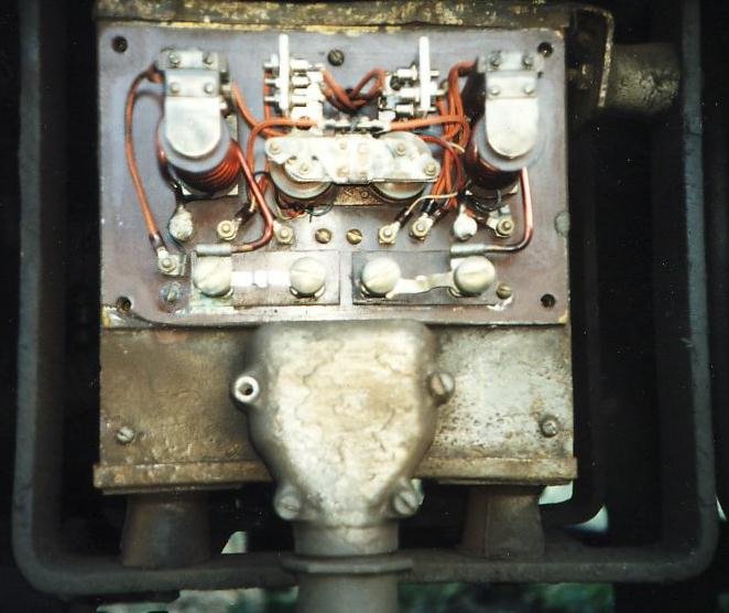
The nasty antiquated mechanical control box for two AC8 alternators. Cover removed in this shot to show the innards. The big silver(ish) box it is bolted to the side of houses the two three-phase rectifiers on huge convection-cooled heatsinks. At the bottom is the output terminal box.
The two big coils (left and right) are the current controllers and the two small coils (centre) are the voltage controllers. Top centre are the small rectifiers to supply the field current. I understand these were a mod to make the alternators self-excited; previously fed from the main control supply wires 33 and 34. Below the voltage coils are the two fuses, one per alternator.
It works by the field supply going through contacts on the current and voltage controllers - if the voltage gets above a preset level, the voltage controller contacts open and turn off the field supply. Ditto current controller. It's all very crude and gets unreliable with age, relying as it does on mechanical things for calibration. I plan to do an electronic conversion on these now I have a spare
Brushgear Maintenance
This is worth carrying out perhaps once a year, or more often if a vehicle is used a lot. It is easy enough on the later AC203; simply remove the two covers at the non-driving end, and then the brushgear can be disconnected, unscrewed and removed as a complete item very easily. The AC8 is less straightforward - remove the small side cover, and then use a length of stiff wire to lift the brush springs out of the way to permit brush removal. Be careful not to lose the springs inside the alternator! It may prove quicker to remove the alternator to do this. In both cases, check for oil or grease contamination - if evident, then the alternator will have to be dismantled, cleaned and sealed up properly.
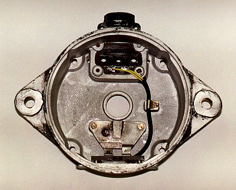
Image 2 - the free end casting, with brushgear assembled. Note how far the brush holders (the rectangular bit below the centre hole) is from the inspection cover (at the bottom) ... see Inage 5. The wires go from the field terminals to the connections to the brushes. The other three holes will take the three output terminals which are attached to the stator (image 4).
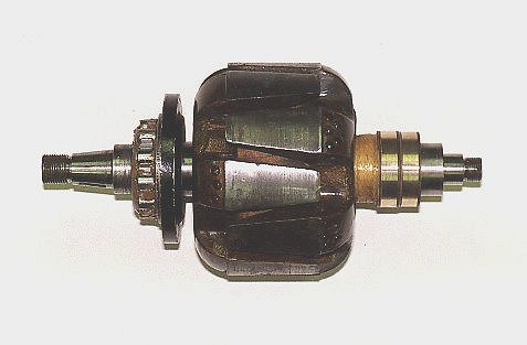
Image 3 - the rotor assembly. Slip rings skimmed on a lathe to return them to being circular, albeit different diameters. This doesn't matter as the new brushes weren't shaped to fit anyway. Unlike starter motors, the current is very small (an amp or two) so the brushes will cope fine even without being shaped. The main 'lump' is the actual field coil assembly; just to the left of that is the drive end bearing housing (the thin black bit), and the rollers of the drive end bearing next to that. To the left of that is the taper which the pulley sits on.
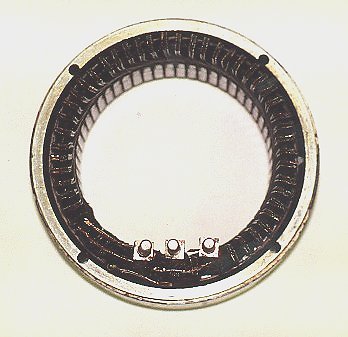
Image 4 - stator assembly (i.e. the main coils). Not very interesting but it's one of the few pics that came out right! The three bolts at the bottom are the output terminals.

Image 5 - inspection cover. The brushes will go either side of that central bit. Slip rings rather out-of-focus, evidently depth of field not all it could be! This inspection hatch is about 3"x2", so you can imagine how hard it is to do anything much with it still attached to the vehicle, in particular cleaning dirty clip rings. To fit a brush, the spring has to be held out of the way (a small allen key will do) and the brush can then be inserted. Fiddly!!!
Experience shows that simply cleaning the brushgear provides only a temporary solution to contamination problems. Check that the brushes do not stick in their holders on reassembly; if they do then very gently rub with fine abrasive paper or a fine file until they move freely and the springs hold them firmly against the slip rings. Recommended minimum lengths as per the BR manual are quoted as 0.75" (AC8; 1" new) and 0.31" (AC203), although at that length they are probably expected to last another 100,000 miles!
A good modification which I did to another one of these is to bolt all the brushgear to the inspection cover with a 3/8" spacer, instead of to the end casting. Then all the brushgear can be removed for inspection quite easily. Didn't have time to do it with this one though.
Testing
Start one engine and measure the voltage obtained at the charging socket / inspection light socket. It should be in the region 27-31 volts; 28 volts is ideal. If it is virtually unchanged compared to prior to starting the engine, then the alternator is probably producing no output - see below.
If lower than the range suggested then either the batteries are low, or something is defective. Try increasing the engine speed to obtain maximum output and recheck. If above 31volts, the control panel is suspect.
Now check output current - this is easily done with the AC8 by removing the fuse in the control panel and connecting an ammeter instead. With the AC203, remove the 'D+' terminal from the control box and connect the ammeter in series here. Stop the engine before substituting the ammeter, and make sure that both it and any connecting cables can cope with 60 amps. I used a cheap (£6) car accessory gauge from an auto discount store for this. Start the engine again and check output; this should be 10-30 amps at idle depending on type, and up to 60 amps with the engine running faster. You may need to switch the car lights on and start the heaters to provide an electrical load for this test if the batteries are well charged.
And finally - some early AC8 control boxes have a little button and a light on the side which nobody seems to know what it does. It is designed to test the rectifier - with both engines running, press the button and the light should come on. If not then check the bulb; if the bulb is good then the rectifier unit is suspect. Although the alternator will still produce some output, it will not be anything like its optimum.
Fault Finding
AC8 With the engine stopped, undo all five terminals in the connection box on the side of the control panel. Note that it is very important not to turn the alternator whilst attempting to measure resistances, or you will get peculiar readings!Measure the resistance between the two small wires - this should be 15 to 30 ohms. If larger than this, check the brushes and the wires between control box and alternator; less than 10 ohms and you've got a short circuit. Be careful not to bend the wires too much, as the insulation gets brittle with age and exposure to oil. The resistance between any given pair of the three large wires should be virtually zero, and resistance to earth megohms or more. Assuming that all is well, two other possibilities remain; the control box may be broken, or the alternator may have lost its reasily cured but a rather trickier to esidual magnetism. The latter is describe the cure.
AC203 We've not got any AC203s installed to comment in detail, but the electronic control box should be much more reliable than the AC8's mechanical one. The control box isn't adjustable; checking terminals are tight and replacing suspect control boxes appear to be the sensible procedures here. The resistance of the brushgear and rotor can be checked as per the AC8, by removing the 'F+' and 'F-' terminals from the control box and measuring the resistance between the two wires; again 15-30 ohms is reasonable. The resistance between the output cables ('D+' and 'D-') should yield a high reading in both directions. A multimeter with a 'diode test' function should give a high reading in one direction and approx 0.7-0.9V in the other - if substantially less then a diode may have failed.
Post Script
A visit to Tyseley has revealed that there is an electronic conversion for the AC8 control box in existence based around the AC203 one. Also revealed is the numbering scheme: AC8 is 8 inches diameter; AC203 203 millimetres!
Summary
The paragraphs above may make the subject sound vastly complicated, but it isn't really. Simple regular maintenance (checking brushgear and charging voltage) ensures good reliability; most faults are cured fairly easily by checking these items, along with fuses and connections. Only in rare cases is specialist help necessary.