Vacuum Brakes
The Automatic Isolating Valve
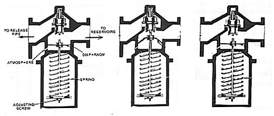
One valve is fitted to each seat of reservoirs, positioned between the reservoirs and the release pipe. Its purpose is to maintain 19 inches of vacuum in the reservoirs even though the vacuum in the rest of the system falls below that figure; this greatly reduces re-charging times.
When the system is initially charged, the vacuum created on the exhauster side of the valves lifts the non-return valve (nrv) off its seat, allowing the air to be withdrawn from the release side reservoirs. When the vacuum above the diaphragm reaches 19" atmospheric pressure under the diaphragm overcomes the spring tension, lifts the spindle and continues to hold the nrv off its seat. Conversely when the vacuum is destroyed, and falls to 19" and below, the atmosphere above the diaphragm will assist the spring to expand and draw the diaphragm down thus allowing the spring of the non-return valve to push it onto its seat holding 19 inches in the reservoirs.