
Wickham Railbus
Elliot Track Recording Coach
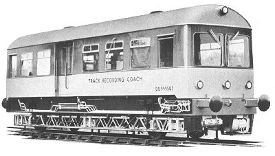
The firm produced another railbus body, almost identical to the others, fitted to much more substantial underframe, for use as a 'Track Recording Coach'. The vehicle could pinpoint and record the smallest of irregularities in track. By a system of electronic measurements the coach verified and recorded on a moving chart the width between the rails, the regularity of track curvature, and by relating axle movement to a high speed gyroscope, cant (where curved lines are banked to exactly the right angle for express speeds).
Back in 1957, special railway vehicles equipped with recording gear designed to record automatically track parameters such as cant, curvature, gauge, or line, had been in use in many parts of the world, including Britain, but no vehicle had yet been produced with apparatus which could give measurements as accurate as those obtainable by manual methods, based on the use of the spirit level, gauge and versine measuring equipment, and at speeds which would not interfere with normal traffic.
Apparatus was at the time available to provide this type of record at low speed and to a medium accuracy adequate for limited purposes, but the improved standard of riding demanded by the public, and the constant search for quick and accurate methods of assessing the quality of maintenance led the Civil Engineers of British Railways to draw a specification of two-axle self-propelled track recording coach for the use of the District Engineers, and to circulate their requirements to British manufacturers.
Their specifications concentrated on the two most important features of curvature and cant, and in particular, the measurement of their relationship on transition curves. The spec. also stated that the coach was to be capable of travelling at speeds of up to 30mph on a rising gradient of about 1 in 100, and to have an internal combustion engine, and suitable transmission, driving and braking controls, and conform to British Railways requirements in general design. The individual axle load was not to be less then 8 tons, and the coach was to be capable of accommodating ballast to give axle loads up to 12 tons to obviate loads under sleepers.
The coach had to be self-contained as regards power supply for instrumentation and other purposes such as lighting and heating, and suitable for testing from an external power supply; the importance of simplicity and reliability of the vehicle and equipment being stressed. It should have seats for three men, excluding the driver.
The average curvature to be recorded was that on a chord length of 33ft to an accuracy of plus or minus 1/20th of an inch or 1% whichever was greater. In addition, the deviation from the average curvature was to be recorded. The problem of achieving measurements of this very high order was chiefly that of obtaining a sufficiently accurate probe system.
The cant or cross level of the rails was to be recorded to an accuracy of plus or minus 7 ½ minutes of arc (plus or minus 1/8 in.), a greater accuracy incidentally than that required at the time for guided missiles. The basic problem in the measurement of cant was the establishment in the coach of a vertical reference which was not affected by the motion of the vehicle travelling along the track or by centrifugal forces resulting from the passage of the vehicle round a curve.
Preliminary Investigation
After discussing the problems with manufacturers, the British Transport Commission placed a design study contract with Elliott Bros. (London) Ltd. to produce an appreciation of the problem which should include the engineering practicability of producing such equipment. A report indicated that it appeared to meet the specification, and the Commission then placed a development contract with Elliot Bros for the manufacture of the prototype coach for operational trial, which was announced in April '57.
Measuring System
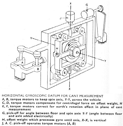
The problem of measuring cant was achieved by using gyroscopic equipment to establish the vertical reference, similar to that used in guided weapon fields, though distributing forces in a railway vehicle were generally more vicious than those found in these spheres. The gyroscope which would be mounted on a platform attached to an axle in such a way that it was always parallel to the traverse axis of the axle but was otherwise free to move. The difference between the gyroscopic vertical and the inclination of the axle (or the platform) provided the measurement required.
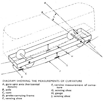
Curvature was to be measured by using a system of three probes (or 'slippers') bearing against the inner face of the rail, the distance between the centre probe and the line connecting the two outer ones giving the offset and a measurement of curvature. Preliminary experiments on a trial probe system over a distance of some 1,800 miles indicated that the required probe accuracy could be achieved, and that the wearing life was satisfactory.
With the vehicle it would be possible to pin-point specific defects in the track which can be rectified in conjunction with present maintenance methods or possibly combined with new principles of maintenance. These were matters which would arise out of the extensive trials that were to be made with the prototype coach when the complete equipment was available.
Delivery
The vehicle appeared about March 1959, in a livery of bright yellow, red and brown (later carrying the red and blue BR Research Department colour scheme). It was powered by a Meadows horizontal under-floor diesel engine developing 97bhp (presumably a further de-rated version of the 105hp one used in the passenger type), driving through a centrifugal clutch and epicyclic gearbox to the forward and reverse gearbox mounted on the driving axle. Gear changing was by electro-pneumatic valves; compressed air and hand brakes operate on the driving axle. Wheels and axles were carried in Timken double-tapered roller bearings. The axleboxes were secured to the frame by radius rods and the suspension was by underslung laminated springs carried in hangers fitted with rubber sandwich inserts. To improve the accuracy of cant measurement the wheels were coned to a taper of 1 in 100. It could travel at any speed up to 30mph when recording and was capable of 55mph when not.
The main electrical supplies were provided by an Enfield diesel generator of 5kW capacity at 230v dc. From this output a Vernons alternator gave the 400 cycles per sec. supply for the gyroscopes and synchros. It was completely self-contained in respect of power supplies for instrumentation and other purposes such as lighting and heating.
Dimensions
Length over headstocks: 38ft
Wheel base: 24ft (the longest all the railbuses)
Wheel diameter: 3ft
Overall height: 12ft 6in
Overall width: 9ft
Weight: 24tons
Axle loading: 12 tons
Fuel capacity: 140 gallons
The coach was developed by Elliott Bros. (London) Ltd., one of the companies in the Elliott-Automation Group, in conjunction with the British Transport Commission Research & Development Engineers. The design and building of the vehicle itself was subcontracted to David Wickham & Co Ltd. to meet the specifications of the Elliot engineers.
Track Recording Equipment
Measurements were presented as traces on Kodak photosensitive paper in the multi-channel recorder which incorporated reflector type galvanometers. The special paper used gave a record which was immediately visible and required no further treatment unless additional copies were required. As the record was being made a previous chart, taken over the same piece of track, could be viewed on an adjacent display. This comparison enabled any deterioration to be seen immediately. Any maintenance work carried out since the previous work could also be checked.
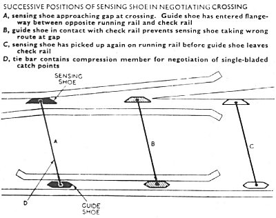
For the measurement of gauge and curvature, the probes were carried from a lattice girder framework supported at the axleboxes. So that the axles could follow the track without restraint, the points of support of this framework were arranged to give the necessary degrees of freedom permitting the axles to twist relatively in both vertical and lateral planes. In addition, 'break-out' springs limited the shock which the framework received when the wheels were subjected to severe vertical accelerations. The sensing probes were spring loaded against the rails and special guide shoes, running in the opposite flange way, ensured their passage through gaps at points and other fittings. At the actual opening in a crossing this guide shoe came against the opposite check rail and prevented the sensing shoe from taking the wrong route.
Operation of Probes
Because of its small size, the probe was an extremely sensitive detecting element of low inertia giving immediate and accurate response to any deviation from line of gauge. When operating, the probes were held down by compressed air and could be withdrawn, clear of the track, when not in use. Raising and lowering was controlled through solenoid-operated valves. There was also a special emergency switch which enables the probes to be retracted by the observer if obstructions were seen on the track. Without stopping the vehicle, the probes could be lowered again on any piece of straight or curved track clear of points or other track fittings. The rubbing face of the probe consisted of a welded deposit which could be renewed when required. When built the vehicle incorporated provision for measurement of curvature on one rail only. Irregularities on the other rail was deducted from the gauge record. Additional equipment to measure curvature on both rails could be readily added.
Measurement of Cant
Cant was measured by comparing the position of one of the axles with a datum provided by the high speed gyroscope mounted immediately above this axle. The spin axis of this gyroscope was maintained horizontal across the coach at all times, enabling the vehicle to operate accurately at any speed within the above limits, regardless of curvature or gradient. Correcting torques were applied to balance the effects of the earth's rotation and to allow for the movement of the vehicles around curves. The use of a gyroscope avoided the significant errors which could occur if a pendulum was used as a datum.
Measurements of curvature, gauge and cant were obtained as ac signals from synchro type pick-offs. These signals were linearly demodulated and the resulting dc signals applied to high sensitivity mirror galvanometers. The record was then produced by these galvanometers on a special photographic paper by the reflected beams from an ultraviolet light source.
In addition to the main measurements, the record included the speed of the vehicle, distance marking, facilities to indicate events such as stations, and space for making notes. The new record together with the 'play-back' of a previous record were both fed through the recorder by a drive taken from one of the axleboxes; a choice of scales was provided.
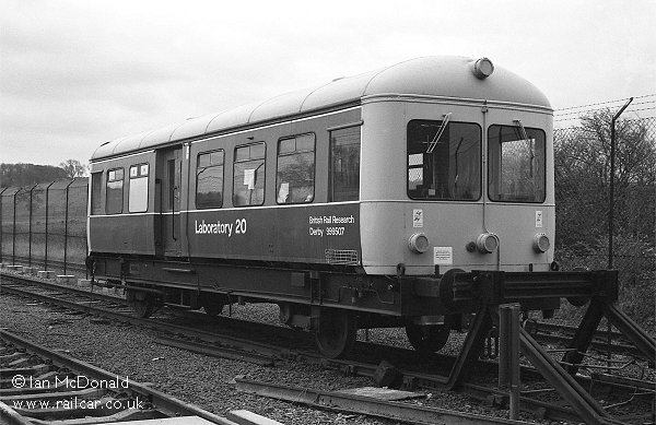
The vehicle is seen at Old Dalby on the 1st Oct 1991. Ian McDonald.
More details
An illustrated look at the history of the vehicle can be found on this website. More details and images of the vehicle at Old Dalby can be found on the Testing Times website.