
Class 124 Swindon Trans-Pennine 6-car DMUs
Description
The vehicles were designed to the same standards of strength and comfort as main-line locomotive-hauled coaches. They were originally designated as the 'Inter Cities Diesel Multiple Unit HL' The HL stood for Hull - Liverpool, and the other Swindon cars had similar designations (EG was Edinburgh - Glasgow, BS was Birmingham - Swansea etc.)
Two types of power car were supplied. The first type had a cab at one end and a corridor gangway at the other. The second type had a corridor gangway at both ends and no driving cab at all and thus placed in the middle of formations. Each six car set, therefore, had four powered vehicles which gave a punchy 1,840 h.p. to enable it to tackle the severe grades on the Trans- Pennine routes. Marshalling was as follows: driving motor composite; motor brake second; trailer first buffet; trailer open second; motor brake second; driving motor composite. The sets had a good power to weight ratio (8.1 b.h.p. per ton) and were thus notable for both their prodigious acceleration rate and for their maximum speed of 70 mph - a considerable improvement on steam performance.
Total seating accommodation was for 292, 60 first class passengers and 232 second class.
Stressed-body Construction
All the cars were 64 ft. 6 in. long and 9 ft. wide at the waist. They had been designed to resist an end-compression load of 200 tons. Buck-eye automatic couplers and BR standard gangways were used. The stressed-body principle of construction with the underframe, bodysides, and roof combined in a single welded structure resisted all bendings, compression, and draught stresses and also left the underframe completely free from conventional trussing, providing maximum space below floor for suspension of diesel and auxiliary equipment and for its subsequent maintenance. The underframe was fabricated from rolled steel sections on to which was welded a corrugated steel floor of special section. This considerably increased the strength of the vehicle in its resistance to end shocks.

The leading-end bodywork of the driver's cab was formed by a single glass-fibre moulding and was a modern styling with swept-back roofline and wrap-round windscreen. The bodysides were of pressed-steel framing members with outside panelling of 16 g. steel; these and the roof were jig-built sub-assemblies. The lower section of the roof panelling was of 8 g. plate which formed a continuous welded structural member extending the full length of the car. The whole interior face of the bodysides, ends, and roof was insulated with sprayed asbestos and the upper surface of the corrugated-steel floor was completely filled with the same insulating material. The floor surface was covered with insulating hardboard. Trap doors in the floor facilitated inspection and maintenance of the diesel equipment.
Windows in the first class accommodation and principal windows in the trailer buffet were double glazed. Beclawat sliding-shutter ventilators were incorporated in side windows throughout the remaining cars. Glass was secured by rubber mouldings (Beclawat's Beclatite system) which gave a flush exterior bodyside and protected the edges of the steel panelling. Bodyside doors, supplied by Lightalloys Limited, were of cast aluminium and incorporated balanced drop windows.
Bogies
The bogies had a wheelbase of 8 ft. 6 in.; they were of riveted construction from rolled-steel sections and fabricated sub-assemblies. The rolled-steel disc wheels were 36 in. dia. Timken roller-bearing axleboxes were provided with manganese-steel liners. Special attention was given to alignment of the horn-guides by mounting the complete bogie frame in a jig while the four horn gaps were machined. This ensured that the renewable manganese liners fitted were all perfectly square without the use of shims.
The side plates were carried on laminated-steel springs with rubber auxiliary bearing springs. The bolster was mounted on nests of helical springs carried on suspension bolts hung from the bogie frame on rocker washers; lateral movement was damped by a large Woodhead - Monroe hydraulic shock absorber. To reduce noise transmission from the track the centre and side bearings were both mounted on rubber.
Vacuum Brakes
Automatic vacuum brakes incorporating two 21-in. vacuum brake cylinders and direct-admission valves were fitted to all vehicles. The cylinders were mounted in the centre bay of the underframe and applied the brake with a clasp action to each wheel. The brakework throughout was bushed with Oilite bearings and was fully equalising. The Gresham & Craven two-pipe system with 15-cu. ft. reservoirs on each vehicle, enabled the brakes to be released almost instantaneously irrespective of the exhauster speed. The passenger-communication and deadman's control on the throttle both incorporated Gresham emergency valves to ensure full application of the brakes.
Underfloor Power Equipment
All the power equipment was supplied by British United Traction Limited. Two engines with transmission and auxiliary equipment were mounted below the floor of each power car. The engines were of the B.U.T.-Leyland six cylinder horizontal 900 Series (Albion 902), with a maximum output of 230 b.h.p. at 1,900 r.p.m. These were fitted with 22 in. Fluidrive couplings. A short cardan shaft and freewheel connected each engine to a four-speed S.C.G. Wilson epicyclic gearbox (SE4) which carried pulleys at the input end for the belts driving the exhausters and electric generator. A further cardan shaft connected the gearbox to the forward-and-reverse final drive mounted on the inner axle of each bogie.
Each engine had its own cooling system, with header tank and fan-cooled radiator driven through a right-angle drive from the front of the engine. The throttle, gearbox, and final drives were electro-pneumatically operated with the E.P. valves grouped together in boxes carried on the underframe; the compressed air was fed from storage reservoirs supplied by air compressors mounted on the engine. The control equipment allowed for a maximum of six power cars to be operated from any driving cab.
The electrical control circuits were carried between adjacent cars by means of four 19-point flexible jumper couplings.
Graviner fire protection equipment, fitted above all the engines, automatically discharged chlorobromomethane from a spray tube on to the engine if the pyrotechnic cord which was mounted above it was subjected to excessive heat. Operation of the fire-protection equipment shut down the affected engine and rang a bell in the driver's compartment. The affected engine could be identified by the driver from the position of the extinguished indicator light. A warning light also appeared at the side of the vehicle showing the location of the fire from track level.
Cab
By the operation of one starting button all the engines on the left-hand side of the train could be started; a second button started all those on the right-hand side. Indicator lights showed when each engine had started and if an engine subsequently stopped for any reason, the failure of one indicator light showed the exact position in the train. The operation of one button stopped all the engines. Indicator lights were also provided to show when sufficient air pressure is available in each power car and that the final drives were correctly positioned for starting. The power-regulator lever incorporated the deadman's handle feature which, when released, closed the throttle and also applied the brakes.
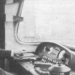
Although it appears that the first cab image shows a vehicle being driven, the lack of brake handle and gear change "spoon" suggests otherwise! Note the two brackets at the side of the window which once held the loudaphone on the unpainted area. The second cab photo shows E51957 taken on the 8th September 78. Syd Young.

Other equipment on the control table comprised the gear-change control handle, vacuum-brake valve, and controls for the dual-note warning horns and windscreen wipers. A hand-brake wheel was fitted in close proximity to the driver's seat and while not fitted from new, provision existed for the BR automatic warning system to be added later. Instruments were grouped together in an improved layout, and included gauges to indicate compressed-air pressure, high and low vacuum in the brake systems, train speed, and engine speed.
Provision was made for two-way buzzer signals and Loudaphone equipment was installed for communication between driver and guard. An adjustable leather-padded driver's seat is provided and there was a specially positioned leather-padded arm rest. Warm air fed into the driver's compartment from the main heating system could be regulated over a wide range of temperatures. A proportion of the warm air could be diverted on to the windscreen for demisting.
The motor brake seconds were wired up ready for easy conversion to driving units if required.
Accommodation
Of the two types of power car the driving motor composites each had open saloons with seats for 21 first class passengers and 36 second class; these vehicles have no gangway connection at the leading end and the driver's cab extends the full width of the car. The motor brake seconds each have accommodation for 48 passengers in six compartments; there are two lavatories and a combined guard's compartment and luggage van.
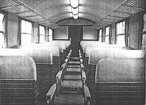
The first image shows the first class area of a motor composite.
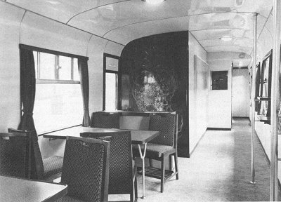
The trailer first buffet car has compartment accommodation for 18 first class passengers. The buffet portion includes a grill and bar; there is also table seating for eight and standing space (pictured). Meals can be served into the three first class compartments. The trailer open second has accommodation for 64 passengers; it has two lavatories.
Interior Decor
Considerable care had been taken with the appearance of the interior of the Trans-Pennine units with the emphasis placed on passenger comfort and appeal.
First class open saloons were panelled in plastic, the walls in Formica tapestry dove grey which contrasted with the partitions of veneered walnut panels. The ceiling was in Formica ivory soft glow. Mouldings round the doors were in polished walnut. The window moulds were anodised aluminium and windows were furnished with curtains of grey fabric. Luggage racks of anodised aluminium ran the complete length of the saloon on both sides. The seats, which were a new profile, were built on a tubular frame supplied by G. D. Peters & Co. Ltd. Seat fillings of Dunlopillo were upholstered in blue and black cut moquette. They were in a 2 + 1 configuration. The floor was covered with a charcoal-shade linoleum and mist blue and black carpet runners.
The finish of the first class trailer cars was generally similar to the MkI first class coaches. The compartments and corridors were finished throughout in polished veneered timber, sapele mahogany surface in compartments and Formica tapestry dove grey in corridors and vestibules. The luggage racks and other metal fittings were in anodised aluminium. The seats were upholstered in a blue and black moquette.
The decor in the second class saloon is very similar to the first class saloon with the exception of the partitions which had opaline green softglow inset panels above and below the windows. The floor was covered with linoleum coloured pigeon grey marble. Blue, grey, and black seat moquettes were used for smoking compartments and green with black for non-smoking compartments. Headrolls were of a light fawn Vynide. Seats were in a 2 + 2 configuration.
Second class compartments had walls of Formica tapestry dove grey with ceilings of Formica ivory soft glow. Seat moquettes were as in the second class saloons but without the Vynide headroll. The buffet saloon was decorated with Decoplast ribbon blue hopscotch pattern and Formica pantomime lavender.
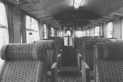
Pictured is the second class saloon of the DMC. It is very similar to the Class 126 Inter-City units.
The lavatories had walls finished in Formica tapestry dove grey to harmonise with the aluminium metal fittings. A primrose yellow suite was fitted in the first class and a white suite in the second class. Floors were covered with Armstrong Accoflex tiles.
Fluorescent lighting was installed in the first and second class saloons; each fitting incorporated a transistor-invertor unit, tube, and shade.
Control of Combustion Heaters
Heating was by means of two Smiths combustion air heaters in each car mounted under the floor. Warmed air was conveyed through ducts to the interior of the vehicles. On compartment vehicles warm air discharged through apertures under each seat and passenger-operated temperature controls were provided on each side of the compartment. Surplus warm air not required for heating compartments was discharged through grilles into the corridor. In open saloons warm air was also discharged through apertures below the seats but the temperature regulation was fully automatic with operation of the heaters controlled by a wall thermostat mounted in the saloon. In warm weather all the heaters could be switched off and filtered air, at ambient temperature, circulated throughout the car.
Modifications
Headlamps
These were first noted during the week commencing 6th January 1964 when a set with E51957 worked the 6.00pm Liverpool-Leeds service with a pair of Lucas car headlights fitted at each end to supplement the normal headcode indicators[1]. Whether this was an experiment with temporary lamps is not known, but I have not come across any images of green-liveried vehicles with headlamps.
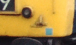
In time a more permanent headlamp would be fitted to some vehicles, to the lower right side of the headcode box, and seems to be a lamp surrounded by a black rubber inside a protective steel circular protrusion, as seen in the image. The right side lamp bracket was also altered to move the bracket to the right to provide clearance from the new headlamp, with a plate over the original bracket holes, or the new bracket as an extension to the existing one.
The vehicles that are certain to have had had the headlamps fitted are 51955, 51957, 51958 and 51961. Others may have had them - such as 51953 (see p31 of the 1973 DMU ABC) and 51954 (p198 of the Brian Morrison book), but if they did they were very short lived, and after removal they show no signs of having carried them.
For the four vehicles that are certain to have carried them, the headlamp on 51958 did not last long (removed by 1976), but the replacement bracket remained as a sign it had been there. E51957 had its headlamp removed circa 1980, in its place was left a circular blanking plate (and the alternative lamp braket was kept). The other two vehicles (51955/61) seemed to carry them until withdrawal.
Other changes
After a few years the engines were derated to 200hp.
One of the problems with the motor vehicles was it's coolant system. Engines were prone to cutting out in hot weather due to a loss of coolant, and it became not unusual for the sets to require topping up during a Liverpool run. This delayed the engine removal scheme as if a 4-car set with only four engines lost the use of an engine it would seriously effect timings over the steep Hope Valley line.
When built the cooling system was an unpressurised type known as a 'through flow system', in which the coolant passed through continuously through a long and shallow header tank, as well as the engine and radiator. When the engine was started some coolant was lost through the overflow in the tank, and, when running over the undulating Manchester - Leeds section, movement in the tank caused the float switch to shut down the engine automatically. They were difficult to top up, as the filler nozzle was located below the solebar.
As the cars passed through Doncaster around 1980 a pressurised 'make up' system was fitted. Now the coolant didn't pass through the header tank which simply fed into the system as required. An additional header tank was fitted above floor level and above the original one to ensure adequate supplies. The filler nozzle was repositioned to the bodyside as on other DMUs. The MBSs due for engine removal did not receive this modification.
In 1981, with a view to making savings in maintenance costs, ten of the motor brake seconds were converted into trailer brake seconds by removal of the two engines from each vehicle. At the time many of the now 4-car sets had three power cars but the additional hp/ton was not suffice to increase timings enough to justify the costs of keeping them running. The work would have been done sooner were it not for the coolant problems mentioned above. As the batteries still required to be charged on these vehicles, the final drives were left in place and connected to the alternator which in turn charged the batteries. The wiring and technical alterations were undertaken by Botanic Gardens depot and this innovation worked well.
Both the Class 124s and 123s (which later joined them) have had various modifications effected over the years to improve their performance and the more notable ones, some of which are readily visible are repositioning of the silencer on the end of the vehicles (staggered so as to prevent collision when matched up to other vehicles), stabilising the gearbox control air supply whereby all the gear changes were undertaken with the use of a constant air pressure (which thus prevented damage to the 4th gear), renewal of panelling below windows in compartment vehicles, fitting fluorescent lights in the Class 123 TCK first class sections, fitting headcode marker lights in the Class 124 power cars and removal of the Loudaphone wiring from the same vehicles.
References
- ⋏ p85 March 1964 Railway Observer (Railway Correspondence and Travel Society)