
Class 105/6 Cravens 2 & 3-car DMUs
Description
The body and underframe were of an integral design, with additional framing members on the power car to handle the extra loading of the power equipment, and the large doorway openings in the luggage compartment. The bodyside framing consisted of 1/8 in. steel cold formed sections which were arc welded together to form a complete unit, and the longitudinal members were Corten low-alloy corrosion-resisting steel.
Complete bodyside panels, carbon arc welded on a semi-automatic machine, were arc stitch welded to the body framing on a cast-iron faced skinning jig to minimise distortion and buckling of the panelling. The roof framing was built up as a complete assembly of 14-gauge carlines, with 1/8 in. thick Corten continuous longitudinal members. Galvanised roof sheets were 16 gauge, secured by button welding to the framing.
The underframe was of a patent construction, designed to withstand a compression load of 80 tons applied to the buffers. It was of all-welded construction, the double solebar had top and bottom plates incorporated at the doorways to form a fuel tank for engine and heater fuel. The power cars had a large aperture next to each passenger door for the fuelling point, while the trailers had only one each side (for heating fuel). Engine coolant fillers were also bodyside mounted.
Standard design DMU bogies were fitted, with single bolster and swing links, which were prone to hunting once worn, producing more vibration. The swing links were later removed. They had Timken roller-bearing axleboxes and lateral control bolster dampers. The wheels and axles were supplied by Owen & Dyson Ltd.
Conventional screw coupling drawgear was used and they had light alloy hydraulic self-contained buffers, mounted on fabricated steel studs protruding from the buffer beam. Standard DMU 'scissors' gangways were fitted. The roof extractors were supplied by Greenwood's & Airvac Ventilating Co. Ltd.
Depending on the depot, the power cars carried shed allocation plates on the solebar (on both sides) in the early days.
Power Train
The B.U.T. standard 150 h.p. power train and components were used, with rubber mountings on gearbox and engine suspension. Vehicles 50359-72 had Leyland 680 engines (see note in modifications below), the remainder had AEC 220s. On the power car the generator and two Clayton exhausters were driven from the transmission by vee-belts. Engine mounted compressors delivered 13 cu ft/air/min at 1,000rpm, and radiator fans were also engine driven via right angle drives.
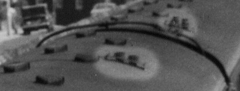
Exhaust pipes were led upwards from the underframe to roof level through a boxed section in the guards compartment on DMBSs and beside the toilet on DMCs. Special insulation and silencing was provided within the enclosed partition. This system was unique to the Cravens vehicles and 4-wheel railbuses. In the image the exhausts are highlighted on the roof of a power twin, they were on the drivers side on a DMBS (closest) and the opposite side on a DMC (which also has the water filler pipe for the roof tank for the toilet).
J. Stone & Co (Deptford) Ltd supplied the 150 amp Tonum generator and control panel. The battery was formed of B.R. A2 type lead acid cells, which had a 440 amp-hr capacity. A Smith-Stone speed indicator was fitted to the bogie adjacent to the cab, and a Smith-Stone distance counter was fitted to one axlebox on the inner bogie of the power cars.
Graviner fire extinguishing equipment was provided, being an electrically controlled spray system. If a fire was detected the engines would also automatically stop, a warning light appear on the fire control relay box on the underframe and a bell ring in the cab. This could be stopped from a switch on the fire control relay box, and if the fire restarted the thermostat remade the circuit to give further warning.
What did a Cravens unit sound like? This sound clip is a recording of a set departing from Ramsbottom on 2 July 1971:
Brakes
Brakes were the standard Gresham & Craven quick release type, originally with 22 inch cylinders on the power cars and trailers. Brake valves were provided in the guards and drivers compartments, and a handbrake wheel was fitted in each cab. The same firm also supplied the passenger communication equipment.
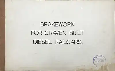
This BR booklet listing all the parts of the brakework along with part and drawing numbers.
Download PDF (10.1mb)
Modifications
Eastern Region sets were noted as being fitted with AWS around May 1961. One set, 51269/56427 had to be removed from the 20:03 Kings Cross - Hertford North on the 11/5/61 due to dragging brakes. It was noted in traffic shortly afterwards with the AWS equipment removed!
The 21" rolling ring vacuum cylinders later became standard, and these replaced the 22" sliding band type.
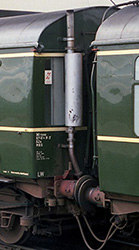
Some vehicles were modified to the normal style of external pipes either side of the gangway, as seen in the image.
Some cars had bars fitted to passenger doors for use on lines with restricted clearances.
Allistair Taylor notes that "cars 50370/1 had Leyland engines when built but were converted to AEC ACX220s at some time early in their careers. This may have been done at Hull Springhead works when the inspection hatches where put in, if memory serves the Leyland cars did not have these when withdrawn."