
Class 103 Park Royal 2-car DMUs
Description
In common with other DMU builders, the designers considered that the use of orthodox separate body & underframe construction would produce an un-favourable power-weight ratio, and achieved the required structural strength with the necessary weight reduction by using an integral steel design.
This was based on a frame, not self-supporting. Two 8in x 3in channel section longitudinals of standard rolled section threaded through folded channel transverse members (a patented feature) which tapered up to the 5/16in m.s. fabricated two section solebars. When the body sides were erected, an additional 5/16in thick m.s. angle was welded the full length of the solebar bringing it up to a depth of 15in with interval stiffening beneath each doorway opening. Drawgear and buffing loads were distributed throughout each end of the frame by diagonal members and plating, taking the main component of these loads to the bolster, a fabricated assembly based on two boxed transverse members. The complete frame was welded together in one jig following setting up, and incorporated the required camber.

The bodyside structure used 14g m.s. top hat section pillars welded on the inner face to the angle solebar extrusion members, and these, together with "top hat" and Z-section longitudinal members were jig welded in units before panelling. To minimise distortion, the exterior 16 s.w.g. exterior panelling was welded into bodyside units, clamped to the bodyside framing units in a welding fixture and welded to the pillars through vertical slots in the pillar faces.
To achieve the necessary distribution of stress concentrations in the body side and underframe shown up in the stress diagram, a deep cantrail was essential and achieved by the use of a 15 inch deep 10 s.w.g. exterior core panel in one piece running the full length of the body. The roofsticks were two aluminium alloy angles spaced by 1/8 inch alloy connecting plates. They were connected to gussets welded to the Z section longitudinal member at the top of the roof stress panels. The roof panels were 16 s.w.g. aluminium alloy, riveted to the roof sticks and overlapped and riveted to the stress panels. The exterior cove panel, combined with the double angle roof sticks and a connecting channel lower cant to pick up the pillars, resulted in a structure of great stiffness, particularly in the longitudinal stress concentrations.

During static load testing a maximum deflection on the frame line of 1/8in was recorded with 200% overload, with consistent return to zero on overloading. The main body sides were welded to the set up underframe and the solebar extrusion angle, which formed the body side bottom member, was welded the full length of the solebar. The front and end frames, also jig built units, were then mounted and the complete roof, again a jig built unit, was secured at cant level. Until this stage the underframe remained supported throughout its length with the necessary camber, and only when the complete shell was assembled was the unit self-supporting.
Light alloy Oleo pneumatic buffers and standard screw couplings were used. Two of the channel section cross-members were positioned at the bogie pivot positions, spaced by 5/16 in m.s. plate welded above and below. The bogie design followed the BR standard steel design for railcars, except using folded steel sections on place of rolled members. Standard BR pattern 3ft diameter wheels and axles were used with SKF self-aligning roller bearing axleboxes, and standard pattern BR brake blocks and carriers. The underframe and bogie frames were supplied by John Thompson (Motor Pressings) Ltd, with wheels and axles from Owen & Dyson Ltd. Laminated springs were by Willford & Co Ltd and coil springs by Turton Bros & Matthews Ltd.
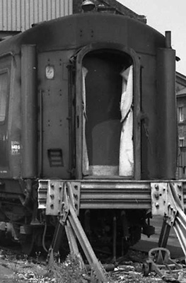
The image shows the rear end of a DMBS, the gangway was of the LMS scissors type. There is only one footstep remaining, there was originally more where the sets of studs were (see this image for an example) which were removed early on. The exhausts (the left one is missing the top part) are unusual in being to the outer part of the rear end, on most DMUs were there to the inside neared the gangway. The DTCLs would not have exhausts but would have water filler pipes running up the ends, as seen in this image.
A two car set with 16 first class and 100 second class seats weighed just under 60 tons, representing 1,150 lb a seat and had 5 hp per ton of empty weight or 4.35 hp per ton when full.
Power Train
Two AEC 220 engines were fitted to the power cars, each rated at 150hp. These were connected via a fluid flywheel and freewheel to a Self Changing Gears R14 Wilson epicyclic gearbox, giving a choice of four gears. From this a cardan shaft went to the axle mounted final drive, which was a reversing gearbox.
Two engine mounted Westinghouse compressors supplied the air for engine, gearbox and final drive control units, as well as the horn.
Electrical equipment was powered by an engine driven Stones generator and control panel. On the trailer car the generator was bogie mounted and axle driven, and incorporated a reversible drive. Batteries (BR type BR A 2) were lead acid of 440 Amps/Hour. Saloon lighting could be either switched to full or half, and was controlled from either cab or the guards compartment. The main wiring for the lighting, control and heater control circuits was carried in trunking at floor level. The standard DMU heating system of two Smiths combustion heaters was used, ducted to outlets throughout the saloons.
Brakes
Braking was via two 21" rolling ring type vacuum cylinders in the power car and two 18 inch cylinders in the trailers. The cylinders were controlled by the Gresham & Craven quick release brake system. Rotary exhausters were driven by each engine via v-belts connected to the gearbox input shaft.

This BR booklet has diagrams showing the brakework equipment layout and lists all the components with part and drawing numbers.
Download PDF (9.4mb)