
Building a DMU
Part Eleven: Underframe Equipment
Images 100 to 108 in the construction booklet are shown here, and are views taken from a maintenance pit looking up at a completed vehicle showing the underframe equipment. All were taken on July 9, 1956. Some of the images have what appears to be a white horizontal bar, I believe this could be tape over a damaged negative (they were glass plate negatives).
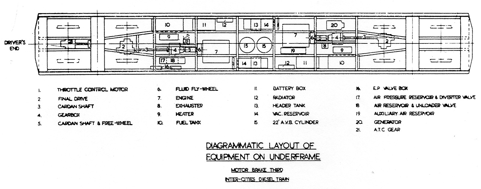
This diagram may give context to understanding the images.

"Underframe Equipment"
Negative 5C143
This view is from beside the bogie at the cab end of a power car, looking towards the rear. The pipe across the center of the image is the fuel tank filler, allowing the tank on the left to be filled from both sides. The vehicles had two fuel tanks, one at each end of the vehicle, so fuelling would mean filling both. They were of equal size, and so presumanbly each one fed one engine and one heater, and not one for engines and one for heaters. On the 5xxxx series Class 126 vehicles the two tanks were opposite one another, allowing them to be connected so fuelling was simpler.
On the back of the fuel tank the small cannister is a fuel filter, the heater is the white tubular object with black bands, on the upper right the cardan shaft is connected via a Hardy Spicer joint to the gearbox, and the fluid flywheel on the engine can be seen behind.

"Underframe Equipment"
Negative 5C142
This is taken from the centre of the vehicle, the cab end behind us, looking to the rear of the vehicle. One of the vacuum brake cylinders is above us. The box on the right contains battery cells, and on the left, just above the exhaust pipe, is the dynamo.

"Underframe Equipment"
Negative 5C141
This is taken from under the engine at the cab end, looking to the rear. The round cover with lots of nuts next to the engine is the oil filter. The large horizontal cylinder on the left is a vacuum reservoir.

"Underframe Equipment"
Negative 5C140A
Taken from under the gearbox at the rear of the vehicle (we can tell by the exhaust pipes). There are four belts coming of the gearbox output shaft to drive the dynamo. A trick for charging the batteries (or testing the dynamo) was to isolate the final drive, and with just one engine running in 4th gear it would be enough to generate an output from the dynamo. The final drive can be seen on the nearest axle on the bogie, above it the corrugated 'key sheeting' which formed the floor. On these vehicle asbestos was sprayed onto the underside for additional insulation, and left exposed.

"Underframe Equipment"
Negative 5C140
We have now turned around, looking towards the cab end. The teeth on the rim of the fluid flywheel were for the starter motor, which can just be seen to the left. The large spring is holding a piece of brake rodding which connected the vacuum cylinders in the center of the vehicle the brake rigging on the bogies.

"Underframe Equipment"
Negative 5C139
Taken from under the final drive at the rear of the vehicle looking towards the cab. Despite being new vehicles, there is a lot a oil sprayed around the final drive and bogie.

"Underframe Equipment"
Negative 5C138
Taken from just under the rear engine looking towards the cab. The two vacuum cylinders are painted black, except on the underside. The flexible pipe from the cylinders goes to a quick release valve, sort of a relay which could admit air to the cylinder without having to travel through all the brake pipes.

"Underframe Equipment"
Negative 5C137
This is the engine at the cab end (no.1 engine / no.1 end) looking towards the cab. The drive belts at this end of the engine drove the water pump (lower) and the radiator fan (right).

"Underframe Equipment"
Negative 5C136
This final image would be used in some of the staff instructional booklets. It is taken at the cab end looking towards the rear. This time we can see one of the air reservoirs, the black cylinder to the right of the gearbox. To the left of the engine fluid flywheel is a thin vertical lighter coloured bracket with square holes, this held the Graviner fire extinguisher bottle.