
Windscreen Wipers
Trico FPK - 375
Service and Repair
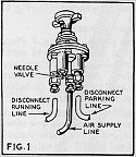
- If wiper does not operate, check control before removing wiper motor. See Fig.1.
- Check air supply to control. If satisfactory - then
- Disconnect running and parking lines from control. Turn to full on. Air should be released from both outlets.
- Turn control to park. Air should be released only from one outlet.
- If air supply is not properly released when checked as outlined above, - then adjust needle valve speed control. Loosen locking nut (5/16") and bottom needle valve gently. Turn back needle valve one half turn and tighten locking nut. With control knob turned on fully and with air pressure normally maintained, the needle valve adjustment made above should permit a maximum ideal wiper speed of 120 single strokes per minute. Conditions may vary on individual vehicles which will require a slight re-adjustment of the needle valve to maintain this ideal maximum wiper speed.
- If the above procedure does not improve the air supply, replace with new control. If control checks satisfactorily, remove wiper and service as follows:
- Remove wiper motor:
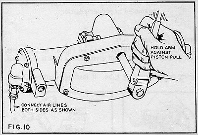
- Check for leaking end gaskets. If leaking, replace gaskets an test wiper. See Fig.10.
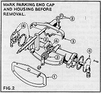
- Inspect shaft and driver assembly If defective, replace assembly. See below - also Fig.2
- To disassemble wiper motor - see Fig.2:
- Remove stamped cover plate.
- Remove shaft retaining ring and thrust washers. Remove shaft assembly.
- Remove top casting and pinion assembly.
- Remove end caps, (see note) and push piston assembly out of housing, being careful
not to damage piston packing.
NOTE: Before removing end caps, mark parking end cap an housing so end caps will be reassembled in proper position. - To repair wiper:
- Check piston packing for wear or cuts.
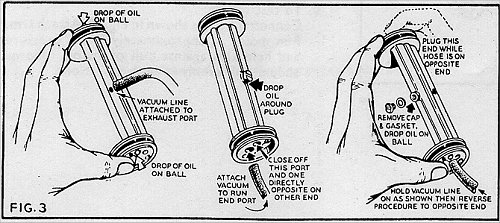
- Dismantle piston and test rack with vacuum (see Fig.3) at ball seats. Place a drop of oil around each ball; if oil disappears a leak is indicated. Replace rack.
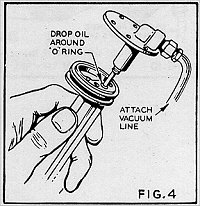
- Test seal of O-ring around running tube. If leaking, replace O-ring. See Fig.4.
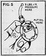
- 4. Test parking end cap and plunger assembly. See Fig.5. Apply air pressure approximately 5lbs. to inlet. Place a few drops of oil on parking plunger assembly. If oil bubbles appear, plunger is leaking. Replace plunger assembly and re-test.
- Check pinion assembly for wear. Replace if necessary.
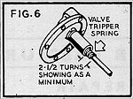
- Place valve tripper spring on running end cap. Not less than 2 to 2 1/2 turns must extend beyond spacer. If spring is short, replace with new spring. See Fig. 6.
- To reassemble motor:
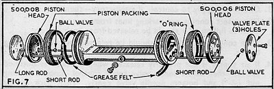
- Assemble piston. See Fig.7. Place packing on running end of rack; insert one short pushrod and one ball valve. Attach piston head 500006 and valve plate (3 holes) with shoulder screws.
- Place packing on other end of rack and insert one long and one short push rod, and one ball valve. Attach piston head 500008 and valve plate (2 holes) with two shoulder screws.
- Soak grease felt in grease and insert in rack.
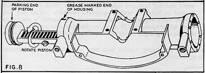
- Grease marked end of housing. See Fig.8. Insert piston assembly slowly. Rotate
piston assembly as it is pressed into the housing, being careful not to damage the
packing. After piston is in the housing, grease both ends, greasing lightly on
park end.
CAUTION: Make sure parking end of piston is in marked end of housing.
- Assemble end caps in proper position being sure markings are matched. Running tube must slide freely in O-ring.
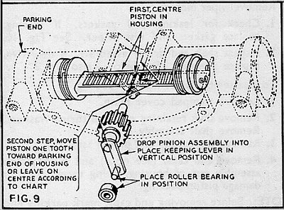
- Centre piston in housing. See Fig. 9. Leave in this position or move piston according to chart below. Fit gasket in top casting and press pinion shaft in place. Pinion assembly must centred with lever in vertical position on housing and tighten four screws. Place roller bearing on pinion lever.
- Grease drive lever track and install shaft assembly, thrust washers, and secure with retaining ring.
- Attach stamped cover plate.
- To test motor: connect motor as shown in Fig.10. Attach arm. Run motor at approximately 5lbs. pressure and hold arm against pull of piston. Motor should pull evenly in both directions.
| Arc of Wipe | 33º | 60º | 65º | 70º | 80º | 90º | 100º | 110º |
| Assembly of pinion Assembly with piston | Off Centre | Off Centre | Off Centre | Off Centre | Off Centre | On Centre | On Centre | On Centre |
Thanks to Trevor Daw (DMU Group (West Midlands)) for the loan of the brochure.