
Blue Pullman
Auxiliary Power
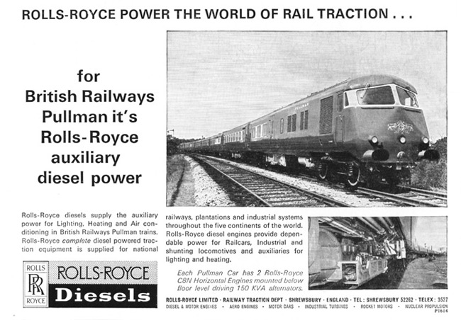
Current for lighting, air-conditioning, refrigeration, battery-charging and ancillary equipment was supplied by two underfloor mounted generating sets, each set comprising an 8-cylinder Rolls Royce C8N horizontal engine directly coupled to a Stones Tonum alternator.
The engine-alternator sets were carried on the vehicles adjacent to the power cars. In the six-car trains this was the Type 4 kitchen cars and in the eight-car trains they were underneath the Type 3 second class parlour cars.
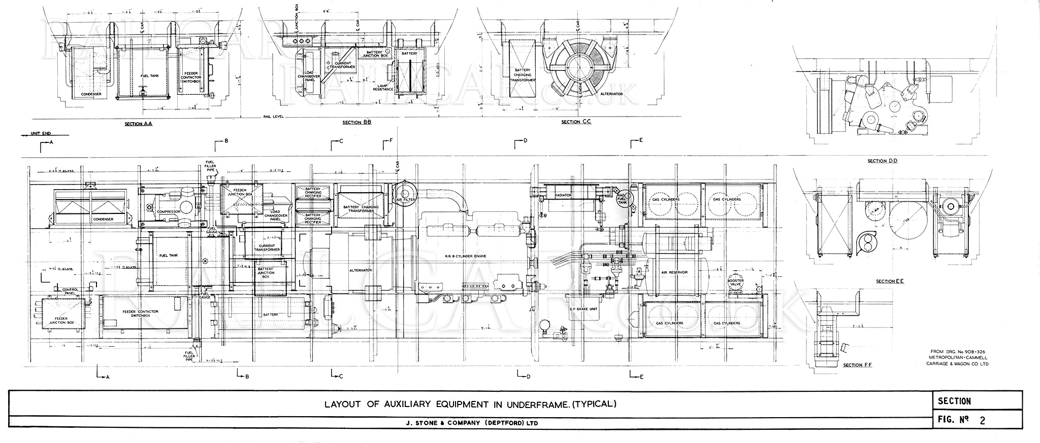
The diagram below shows the layout of the equipment on the underframe.
The output of one set was considered sufficient for normal winter and summer requirements, the second set was carried for use as a standby and for use under extreme conditions. The engine was rated at 190hp at 1,500 rpm and the three-phase 50-cycle alternator at 133 kVA, 400v.
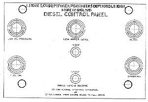
Right: The auxiliary engine control panel. Clockwise from lower left the lights indicated fuel on, low oil pressure, low water level, idling and starting. The two smaller centre buttons were for start and stop.
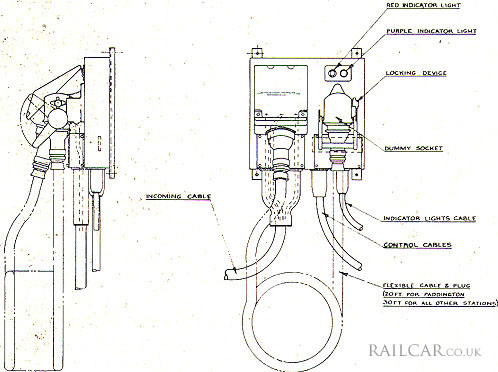
Provision was also made for the operation of the lighting, refrigeration and air-conditioning equipment from an external three-phase a.c. supply when the train was stationary. Static power supply points were provided at terminal stations on the routes served by these trains. The junction box for the 120kW shore supply is shown on the left.
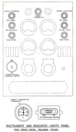
The 400v a.c. three-phase 50 cycle power for lighting and air conditioning was distributed by two four-wire feeders running the length of the train. Connections between the cars were made through Stones Kleops intercar couplings, and the circuits so arranged that if a coupling was broken the feeder was immediately disconnected from the power supply. The bulk of the lighting was supplied at 230v a.c. by phase-to-neutral connection of the 400v feeders, and the remainder was supplied at 110v a.c. from a 230/110v lighting transformer. The compressor, condenser-fan motor, and the floor and air heaters were connected to the three-phase 400v supply.
The air-conditioning fan motor and the control circuits were supplied at 24v d.c. from a three-phase transformer/rectifier unit. This supply was also used to charge a 24v 216 Ahr battery for auxiliary engine starting and emergency lighting.
Right: The instrument and indicator lights panel.
Mike Boot, who had a long railway career including time in the LM Region DMU Specialist Engineers section at Nelson Street, recalls this from his time at Derby: "When I went into 25 Shop as an apprentice they were overhauling two types of RR 8 engines - one was an 821 and the other the 823, used on the Class 127s. The 821 was very different to the 3 in that it was the auxiliary engine for the Blue Pullman and had a big alternator hung on the end, but significantly the exhaust manifolds were water cooled! Also the oil cooler was slightly larger than original on the inside of the sump. Soon after these engines and the spares were converted to 823’s."[1]
References
- ⋏ Email Mike Boot to Stuart Mackay 23 January 2021