
Blue Pullman
Bogies & Couplings
Leading and power bogies had a 9' 6" wheelbase, the remainder were 8' 6".
The permanent type of coupling between the coaches, which absorbed both buffing and drawing loads, was designed to provide a smooth pick-up on starting and stable running at high speed. Normal coupling hooks, for emergency use, were in concealed recesses in the nose of each of the motor cars.
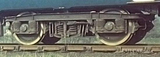
The bogies were of the Metro-Schlieran frictionless type incorporating hydraulically damped helical springs. An example is shown here under a Type 6 Parlour car.
The hydraulic dampers fitted to the bogies were supplied by Armstrong Patents Co. Ltd. The 2nd (inner bogie of the power car) and 3rd (on the outer bogie of the vehicle attached to the power car) bogie from each end were each fitted with two fully suspended traction motors, making eight axles motored on a train of either six or eight vehicles.
The unsprung weight on the axle was reduced to a minimum by carrying the motor on a three-point mounting on the bogie-frame. To accommodate the relative vertical movement of the axle and motor the motor drive was taken through a Brown Boveri spring drive unit. On the motor shaft was mounted a single-helical reduction gear meshing with the axle-drive gear which was mounted on a quill shaft carried on roller bearings. In the face of the gear was a ring of spring-loaded pads which engaged with face-dogs integral with a spider pressed on the road wheel hub. Thus the gears were maintained at the correct centres while allowing free vertical movement between axle and motor.
The motors were GEC four-pole self-ventilated machines with a continuous rating of 425A 383v, 199hp at 1,360rpm and a gear ratio of 19/67. The two-motors in each power bogie were in parallel. Current for the inner-vehicle power car motors was supplied through cables attached to the adjacent power car.