
Waggon und Maschinenbau Railbus
Description
The body contour was designed to comply with the British Railways C1 loading gauge. The through-length body underframe which carried buffing and drag forces consisted of channel shaped cross beams which were welded to the longitudinal girders. Stresses produced by the power equipment were transferred to the longitudinal girders by parallel and transverse braces of flanged plates. To increase rigidity a corrugated plate floor was connected to the frame. This was welded to the longitudinal and cross beams by stitch welding. A 22.8 inch deep side apron was welded to the solebars to provide an extension to the bodyside panels. The bodyside framing was formed as a light steel structure, the bodyside pillars were z-section pressings. The side and roof sheeting were of light alloy sheets, riveted to the body framing. The roof plates were crimped longitudinally to provide maximum rigidity. End sheets were of light gauge steel. The body was suspended elastically and swung from four points of the running body frame. The vertical deflection of the body was absorbed by hydraulic shock absorbers, as was the side vibrations. Traction stresses produced by the power equipment were transferred to the longitudinals by parallel and transverse braces of flanged plates.
The underframe was a rectangular structure comprising two longitudinal side girders and two headstocks of rolled sections welded together. Further longitudinal and transverse members were fitted as necessary to carry the diesel-mechanical power unit and give ample rigidity to the frame.
The axleboxes for the SKF roller bearings were carried in Ferrozell type adjustable guides. Ferrozell was a wear-resistant material which did not need lubrication and had been used with success by the German Federal Railway for some years. The axle longitudinal and tranverse clearance of 0.5 mm each enabled smoother riding when negotiating curves. The buffers, as in German practice, were arranged with one flat and the other convex-surfaced at each end of the car. On trials the riding proved very good, with an absence of appreciable oscillation or undue vibration. The light wheel sets with double waved wheel discs and solid axles were carried by six-plate laminated springs through adjustable spring screws on the underframe. Each axle was fitted with two brake discs by which the brake was applied through brake shoes which had a lining of synthetic material. The vehicles were equipped with Knorr automatic compressed air disc brakes. In the event of a failure causing reduced pressure of the brake pipe, the brakes were automatically operated.
Power Train
The underfloor mounted Buessing 6 cylinder diesel engine developed 150 h.p. at 1900 r.p.m. The supply of fuel to the engine was pneumatically regulated by a foot operated valve installed in the drivers cab and by a governor fitted to the engine. In the case of a failure of the pneumatic throttle motor, the engine could be controlled by a hand lever. A governor on the Bosch injection pump limited the speed when running idle. A push button was fitted to the drivers panel to allow the driver to stop the engine electro-pneumatically. The air intakes to the engine was via a Delbag type exchangeable filter element fitted in the vestibule. The exhaust was taken away by a pipe passing through the roof of the car, the pipe being insulated against heat and sound.
The engine cooling circuit comprised a large underframe mounted radiator with a Behr type hydraulic fan drive, automatically being kept within a limit of 70-80 degrees centigrade. A diesel-fuelled Webasto water heater could be used to pre-heat the engine before starting. These used a lot of current (they had glow plugs) and possibly account for the number of flat batteries in BR days. The coolant could also be passed through four floor-mounted radiators. There were two of these in each saloon fitted under seats, and with an electric blower unit fitted to them provided the saloon heating. and two defroster devices were interconnected with the engine cooling system.
Power was transmitted through a fluid flywheel and by cardan shaft to the ZF electro-magnetic six-speed gearbox. The six speeds were electrically selected by the driver, and operated by electro-magnetic multiple disc clutches. The six-gear ratio allowed full use of the engine power curve. Drive from the gear-box to final drive was again by conventional cardan shaft. Final drive torque was transmitted to the frame by means of a flexibly mounted torque arm. Forward and reverse gears were mounted in the Gmeinder final drive unit and selection was pneumatic by a driver-controlled valve. In the event of loss of air pressure the equipment was designed to allow selection by hand through a trap door in the floor.
It should also be pointed out that, uniquely, these vehicles did not have a freewheel in the driveline. While this meant that they could not coast in the conventional sense, it had the very valuable advantage that engine braking could be used almost down to a stop, by changing down gears as required. This was very useful given the propensity of the disc-braked wheels to skid on slippery rails.
Re-engining
Spares for the Buessing engines were expensive to obtain, and three would be re-engined with a more standard AEC 220 150hp engine[1]. E79963 was treated first, then E79961 in early 1963 (at Doncaster Works, noted as the first railbus to receive attention there[2]), E79964 was last.
Coupling
Unlike all the other BR railbuses, these vehicles were fitted with screw couplings and air hoses at the ends, and could be operated in tandem (i.e. a driver in each vehicle but with braking controlled from the leading cab). They were not multiple unit-equipped. The drawgear was rated at 15 tonnes, so a railbus could be towed by another one if required.
A small connecting cable also allowed the communication bell to run through both vehicles, so the driver and/or guard could signal through to the other vehicle. The socket can be seen to the left upper of the centre lower headlight in most photos.
Interior
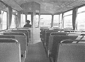
The floor, bodysides and roof were filled with insulation materials to protect against heat and sound. The interior of the car was lined with plywood panels having a clear polish, the ceilings were painted ivory. Rubber glazing material secured the safety glass windows. The upper parts of the body side windows were hinged to provide a limited opening for ventilation. Curtains were provided on the bodyside windows. Luggage racks of light metal construction with hemp mesh netting ran lengthwise just above the windows. The seats were constructed with spiral springs covered by rubberised hair and trimmed in green imitation leather. Arranged in a 2+3 formation facing the respective ends, there were seats for 56 passengers if counting a seat slightly narrower than double width as two which was adjacent to the vestibule in each saloon. There was also room for about 40 standing. The two saloons were identical, divided by the vestibule. The partitions were of wood, without the glass which was standard in the British railbuses, and it was felt this created a cosier atmosphere.
The doors, situated almost centrally on each side of the body, were power-operated under the control off the driver, but a push button above the doors enabled passengers to open them. The doors could also be opened and closed by hand. Luggage room was provided in the entrance vestibule. The header tank for the cooling water, engine air inlet and filter, fire extinguisher and tool/medical cupboard were located in the luggage room, through which the exhaust pipe also passed and the luggage room was curtained off. A letter rack and emergency ladder were fitted in the second luggage area.
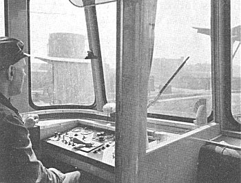
The driving cabs were partitioned from the passenger accommodation. The partition was glazed from waist up and had a door giving access from the saloons. The drivers windscreen was fitted with an electrically operated windscreen wiper and sun visor. The windows had a Schulz defroster, which was heated from a nozzle. An upholstered folding seat was provided for the driver. The rear cab windows were fitted with curtains to prevent light from the saloons interfering with the drivers vision. A small extinguisher was located in each cab. Electrically operated driver-guard buzzers were fitted to the driving control panel. A three tone typhoon (alternate tone) horn was fitted to the roof at both ends. The sanding gear was air operated, controlled from each cab, the sandboxes were installed on the driving axle in accessible positions. The operation of the horn was by foot pedal, the only manual operation being that of the brake and gear lever. The electro-pneumatic deadman's device being a plunger depressed by the driver's left arm. The handbrake was lever operated, and the cab also had a clip to hold the drivers special notices, which was a standard fitting abroad.
The throttle was controlled by a floor pedal, not by a hand control as used on UK-built railcars. The manuals were in German, most of which had been translated into English by Germans. A driver's favourite was the description of the sanding gear, which advised that “gravelling is effected pneumatically”!
Electrical equipment was by Brown Boveri.
After a few years the Buessing engines began to give trouble, and because of the high cost of importing replacements from Germany 79961/3/4 were fitted in 1962/3 with AEC 220X engines. The AEC engine included its own air compressor, so these three conversions had two air compressors and were quicker at pumping the air system up on starting than the two which retained Bussing engines.
The vehicles tare was approximately 15 tons, giving a respectable 10hp per ton, and had a maximum design speed of 55mph.
| Feet | Inches | |
| Length over buffer | 45 | 9 1/4 |
| Length over body | 41 | 10 |
| Width over body | 8 | 8 3/8 |
| Inside width of body | 8 | 4 |
| Overall height | 11 | 9 1/8 |
| Height to floor | 4 | 0 |
| Height floor to ceiling | 7 | 8 1/6 |
| Wheelbase | 19 | 8 7/32 |
| Diameter of wheels | 3 | 3 3/8 |