
Unloader Valve
Description
The BUT service manual tells us:-
The purpose of the unloader valve is to relieve the compressors of the pumping load when the reservoirs are charged to operating pressure.
Air from the compressors enters the the unloader valve through an inlet port (12) and passes through a felt filter (13) along a passage (11) into the unloader valve chamber (5).
When the pressure in the reservoir is below that of the unloader, the spring loaded valve (4) remains closed and air flows via a non-return valve (7) into the reservoir. The non-return valve retains the pressure built up in the reservoir when the compressor is not operating.
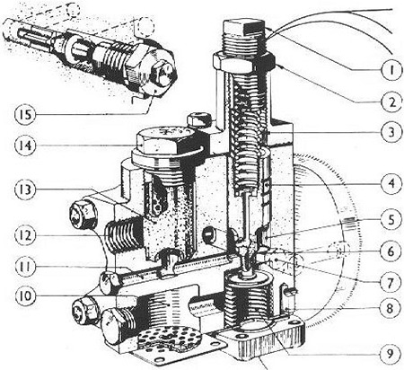
1. Adjusting nut
2. Locknut
3. Spring
4. Valve
5. Unloader Valve Chamber
6. Valve Seat
7. Non-Return Valve
8. Air Passage
9. Bellows
10. Silencing Chamber
11. Air Passage
12. Inlet Port
13. Felt Strainer
14. Plug for Felt Strainer
15. Plug for Non-Return Valve
Reservoir pressure is communicated to the inside of a metal bellows (9), situated below the valve.
When the reservoir pressure exceeds that of the unloader, the bellows are forced up, thus overcoming the resistance of the spring and lifts the valve off its seat.
Air continuing to enter the unloader valve from the compressor is then diverted to atmosphere.
The unloader valve was also used on some buses - it is a Clayton Dewandre model A.P.S.A. 647-1. The original Leyland part no. is 295651/1.