
Fluid Flywheel
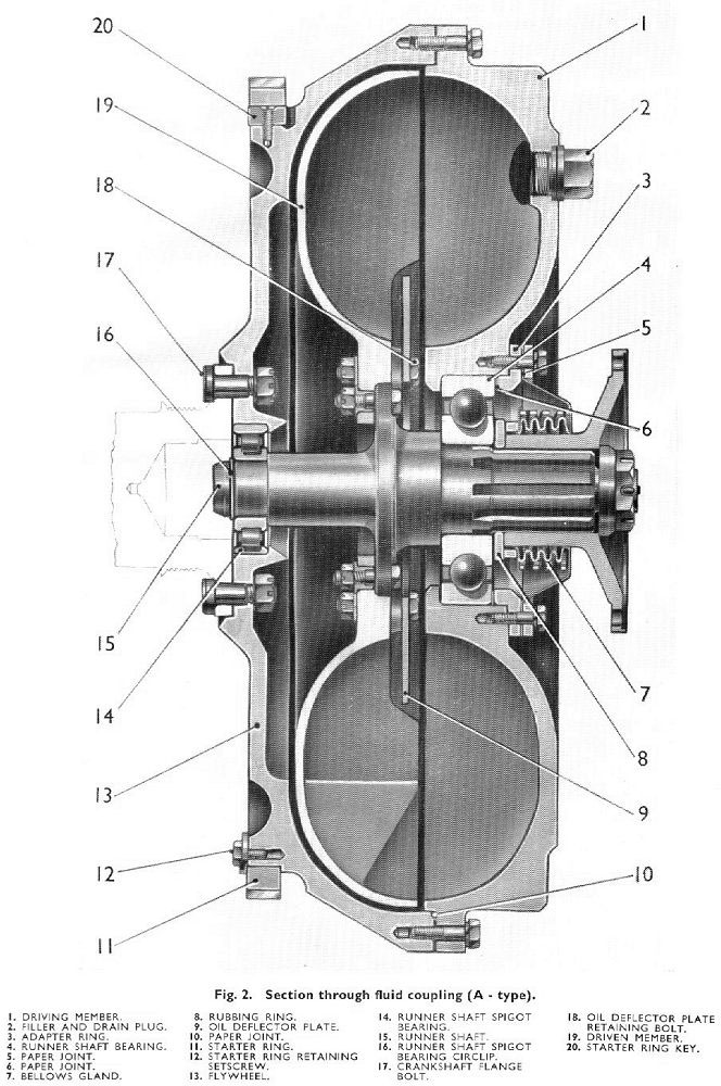
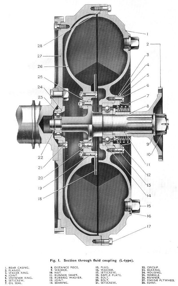
This fluid coupling fitted to both A- and L-type engines consists of two parts: the rear casing which is secured to the engine flywheel (which in turn is secured to the crankshaft); and the runner, which is free to rotate within the outer casing (formed by the flywheel and the rear casing) and is coupled by the joint flange of the freewheel unit.
Left: A-type; and Right: L-type section views of the fluid couplings
The rear casing and the runner are each provided with a series of pockets seperated by radial-webs formed on their inner surfaces.
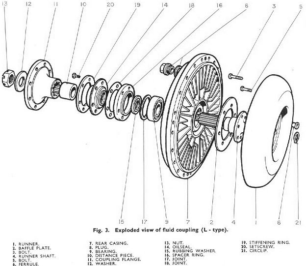
Left: An exploded view of the L-type coupling.
The runner shaft which is bolted to the runner is located in two bearings, one of which is fitted in the flywheel and the other in the rear casing. The flywheel or spigot bearing is located into the flywheel bore on the A- type engine, whereas on the L-type engine this bearing is carried in its own housing which in turn is setscrewed to the flywheel.
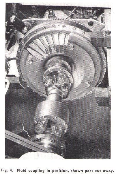
Right: a fluid flywheel in position with a cutaway showing the webs.
A self-adjusting bellows-type packless gland oil seal is fitted to the outer side of the rear casing.
The flywheel is filled approx. 2/3rd full with a transmission fluid, as the rear casing is rotated the centrifugal forces throw this fluid outwards and spinning it, the spinning fluid turns the runner, which in turn revolves the output flange connected to the freewheel.
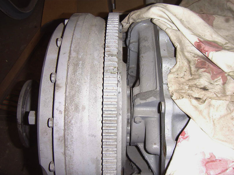
Affixed to the fluid flywheel was a starter ring (shown right), which the starter turned to rotate the engine to start it.
The majority of the fluid flywheels were 20", there were some exceptions such as the Derby Lighweights which had 18" ones. Although the AEC 220 engines themselves were otherwise identical to that on later vehicles, they used a different mounting system.