
Battery Multiple Unit - Derby 2-car BMU
Description
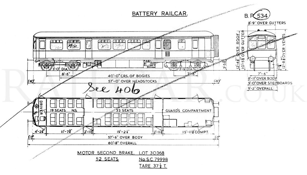
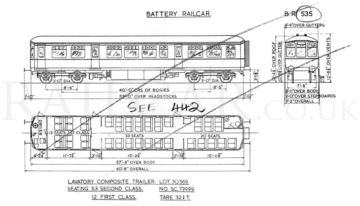
Consisting of a motor car and a control trailer the twin set seats 12 first and 105 second class passengers. The motor car has two 100kW nose-suspendeded traction motors on one bogie, the two compensated motors transmit power through single spur gearing with a ratio of 81/13, and the acceleration was measured as 0.75mph per second up to 30mph. The batteries, totaling 216 lead acid cells with a voltage of 440 and a capacity of 1,070 amp/hr, are spread over both vehicles, so that the empty weight of the motor car is 37½ tons and that of the control trailer 32½ tons. The combined battery weighs about 17 tons, and the underframes had to be strengthened to take this weight. The arrangement of the battery cradle is that they can be partially withdrawn for maintenance and inspection.
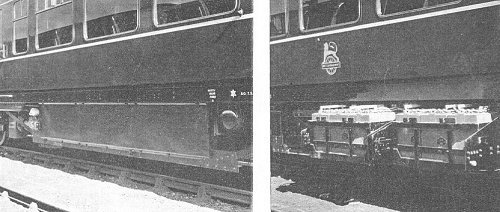
The image shows the battery cradle shown in the closed and open position.
As Germany had considerable experience with battery railcars, such as the German Federal Railway bogie battery railcars of types ETAlSO and ETA1Y6, the North of Scotland Hydro-Electric Board wanted equipment already proven, and so ordered traction and control equipment as built by Siemens-Schuckert and Schaltbau. Control was effected through series and parallel grouping with three positions of field weakening, and with facilities for cutting out either motor. A very smooth acceleration was obtained by cam-operated contractors driven by an electric motor whose speed was automatically regulated by the traction motor current. All the control equipment was located in the guards van with the exception of the starting resistance's which were housed under the motor coach. Without the voltage surges found in full-electric traction, the motors could be made smaller and lighter than standard types, and the limits of the operating voltages were smaller than normal electric traction. With lead-acid batteries the operating voltage rarely varies by more than +5 per cent and -10 per cent, and this facilitated the design of the traction equipment. Further, without the interruptions in the motor circuit due to jumping of a collecting shoe or pantograph, rating conditions for the motors were easier, though it is possible to utilise the motors to a much higher degree than the rated power would normally indicate. Cooling-air for the traction motors was drawn in through grilled inlets on the car sides and transferred to the motors through flexible ducts.
Heating of the two cars was by means of a Smith Webasto oil-burning air heater. This was under automatic electrical control, and the current for this and for car lighting was supplied by a 2.6kW 440-24V motor generator set carried below the motor car floor. An automatic voltage regulator ensured that the output from the generator was maintained constant within very close limits, even the though the main battery voltage will vary according to its state of discharge.
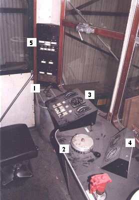
At each end of the train was a full-width driving compartment, containing a driver's desk, into which was built: (1) a master controller, situated on the driver's left, with two handles, one to select forward or reverse movement and the other to control the speed of the train; the master controller handle contains a device which automatically applies the brakes and cuts of all power to the electric motors in the event of an emergency; (2) a brake valve situated on the driver's right; (3) a raised sloping desk accommodating a voltmeter, ammeter, speedometer, switches and indicating lamps associated with the control equipment; (4) a separate panel having two brake gauges on the driver's right; and (5) to the left is mounted a 24V switch panel for instrument lighting, cab lighting, marker and destination lights, and de-misting fan. Stuart Mackay.
An electrically-driven air compressor with a capacity of 17cu. ft. per min. was mounted under the control trailer to provide air for the Oerlikon-type air brakes, the two-tone horn, and the window wiper. No regenerative braking was installed. Electricity supplies, including means for isolating and metering at both glass bulb mercury arc rectifying charging installations, were provided in Aberdeen Joint station against platform 1 (6,600V, 3-phase, 50 cycles ac), and at Ballater station (11,000V, 3-phase, 50 cycles ac). They were also designed to charge the battery at a high rate during the time the train is standing in the platforms during lie-over times at both these stations. Charging was automatically stopped when the battery had received sufficient charge.
The electrical circuits were arranged so that the charging cables could not be connected or disconnected from the train while they were live, ensuring the safety of personnel when handling the cables; and to prevent the train from being moved while the charging cables are connected. To keep the battery cool during charging, air was blown through the battery compartments by electrically-operated blowers. The battery-charging circuit was also interlocked with the blower arrangements so that charging could not take place until the fans were switched on and pipes connected.
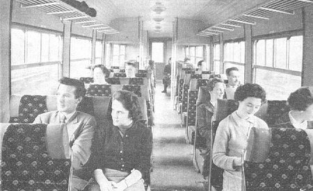
The passenger saloons seemed unchanged from a standard Derby Lightweight.
Livery
The set was delivered in lined green, and it never carried whiskers. It had the lion over wheel emblems until withdrawal from passenger use.