
Coupling Procedure
Diesel Multiple Unit Trains
A filmstrip by British Transport Films.
This was an A4 size booklet of lecture notes and twenty-seven 35mm mounted B&W transparencies: a title slide; 24 slides in the main series; a summary of coupling codes; and a credit slide.
They are thought to be taken at Bristol Marsh Junction depot, the paint/brake overhaul dates on the vehicles are late 1970 so this probably dates the series to early 1971.
The title slide
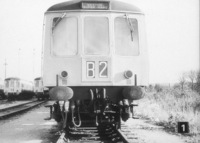
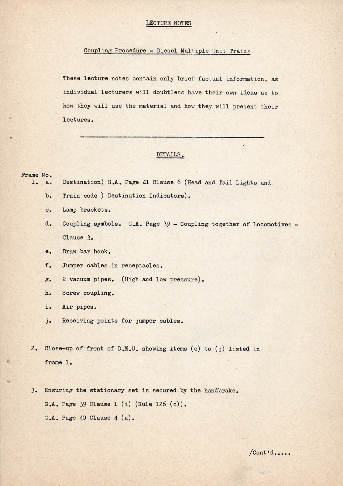
1: This shows the front end of a Class 119 power car, the accompanying notes describe the various items. Note this example has oval buffers, the two to the left have round buffers.
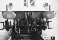
2: This shows the buffer beam front end of a Class 119 power car, the accompanying notes describe the various items.

3: "Ensuring the stationary set is secured by the handbrake".
This is the cab of a Class 119.

4: A Class 120 approaches the 119.
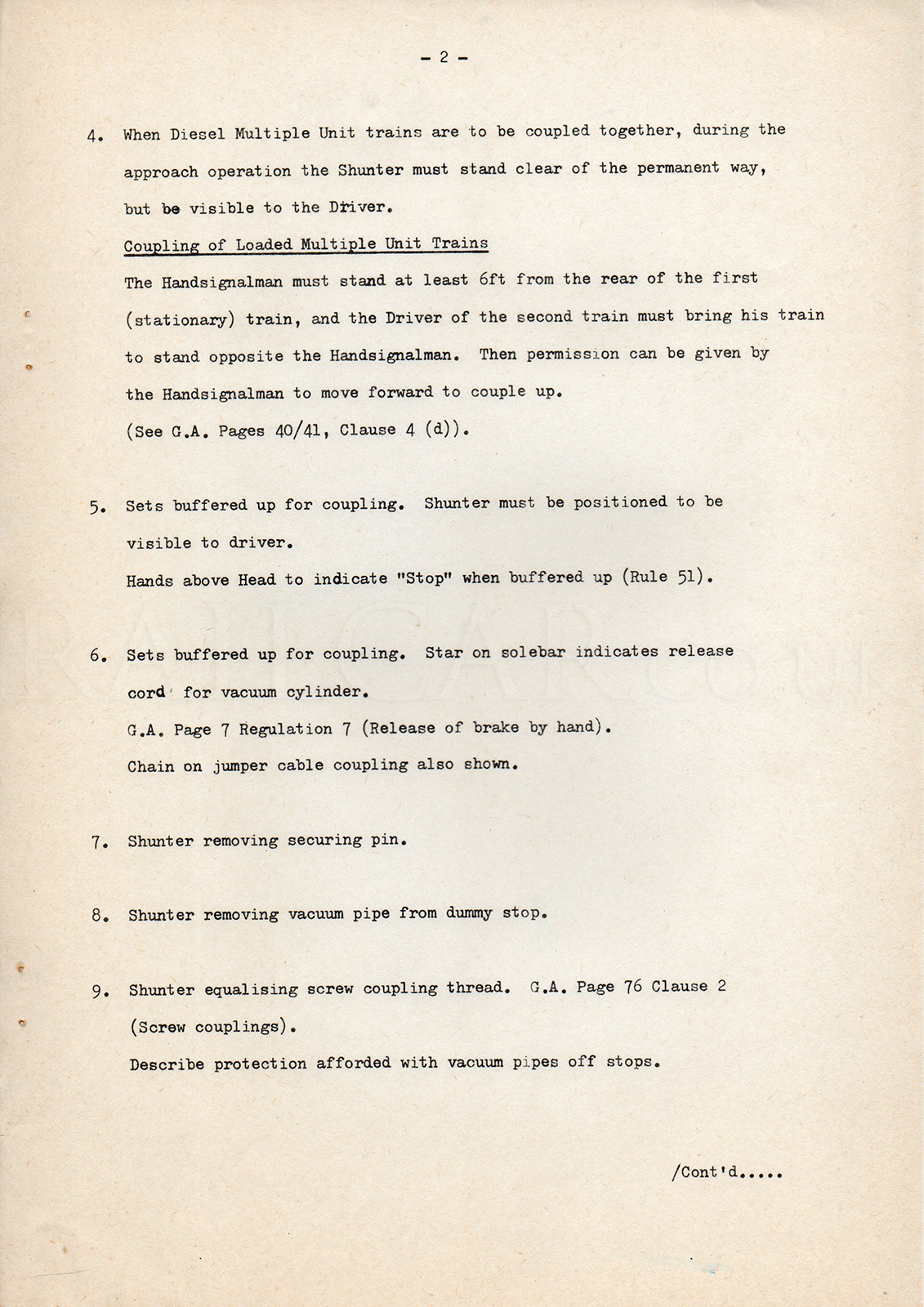
"When Diesel Multiple Unit trains are to be coupled together, during the approach operation the Shunter must stand clear of the permanent way, but be visible to the Driver".

5: "Sets buffered up for coupling. Shunter must be positioned visible to the driver. Hands above Head to indicated 'Stop' when buffered up."

6: "Sets buffered up for coupling. Star on solebar indicates release cord for vacuum cylinder."
The 119 has the star in this place as the vacuum cylinder is fitted to the front of the bogie. The 119 on the left has a brake overhaul date painted on the solebar (B.O. 5.11.70), the 120 on the right (which has the brake cylinders fitted on the underframe in the centre of the vehicle) has the paint date (30.9.70) on the solebar.

7: "Shunter removing securing pin."

8: "Shunter removing vacuum pipe from dummy stop."

9: "Shunter equalising screw coupling thread."

10: "Screw coupling over draw bar hook."

11: "Shunter taking jumper cable out of socket. Jumper cable coupling securing chain shown. Retaining clip to be pressed back and disengaged.".

12: "Shunter coupling up jumper cables. Cable farthest away to be coupled up first." Also "Driver must observe coupling procedure to satisfy himself it has been completed correctly'".

13: "Shunter coupling far side inner jumper cable."

14: "Star valve on air pipe. Star valve must move easily, if it does not air must be expelled from the pipe before coupling of air pipes can be completed."

15: "Shunter coupling air pipes. Vacuum pipes still hanging to afford protection."

16: "Cock in open position"

17: "Shunter holding vacuum pipes preparatory to connecting. Picture shows securing chain fouling end of pipe. Before connection can be correctly made the securing chain must be moved clear."

18: "Shunter completing coupling of one set of vacuum pipes. Both securing pins in position."

19: "Opposite side of train showing shunter coupling up last jumper cable."

20: Coupling-up completed.

21: "Coupling-up completed : ensuring that the handbrake is released."

22: "Shunter or Guard with tail lamp walking to rear."

23: "Tail lamp being placed in position. It is the Guards's responsibility to ensure this is done."

24: "All communication between Guard and Driver is by bell code."
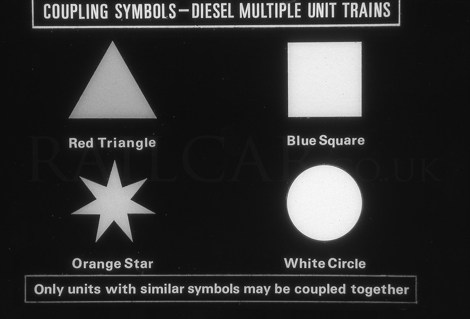
Coupling Codes
Credit slide