Charging Systems
Operation of AC203 Battery Charging System
From a BR Training booklet
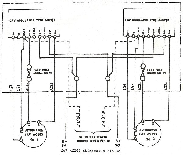
This system consists of the following equipment:
2 x CAV AC203 60 amp alternators
2 x CAV regulators type 460/C3
2 x fast fuses BLET.75
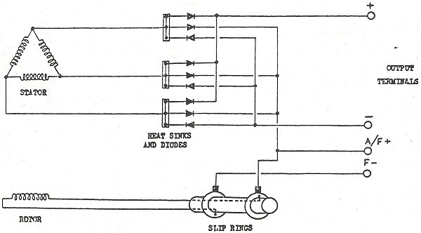
AC203 alternators rectify the generated alternating current electronically and this rectification is normally provided as a built in feature of this machine. Silicon diodes are used in this application.
The use of diodes in this application ensures that no adjustment for wear in service is required and this greatly reduces maintenance. All diodes have a safe voltage and current carrying capacity that the designer ensures is well above the system operating levels, but if this limit is exceeded then the diode may be irreperably damaged. Reverse polarity connections of the battery cause almost immediate destruction of the rectifier diodes.
The AC203 is a self-excited machine which differs from the AC8 alternator in that the rectifying diodes are built into the machine. The output is therefore D.C. which is fed to the regulator. The CAV 460C regulator is a solid-state unit sealed within an aluminium case. On Power Cars previously fitted with AC8 alternators, the regulators (and fast fuses) are housed in the same location as the displaced RUG unit. On Power Cars originally equipped with generators, the regulators are mounted in the box which occupied the Tonum regulator panel.
To prevent the alternator diodes being destroyed by reverse polarity connection of the vehicle battery, a 'fast' fuse is fitted to the NEGATIVE line from each alternator.
The regulator is set for a maximum voltage of:
29.5 Volts - Lead Acid Batteries
31.5 Volts - NIFE batteries